Optically blocked reference pixels for focal plane arrays

Active Publication Date: 2006-06-15
DRS NETWORK & IMAGING SYST
View PDF10 Cites 41 Cited by
  • Summary
  • Abstract
  • Description
  • Claims
  • Application Information

AI Technical Summary

Benefits of technology

[0012] In one embodiment disclosed herein, reference pixels may be configured to be identical to, or substantially identical to, the active detector elements of a focal plane array assembly to minimize divergence in the output of the reference and active pixel elements over temperature, thus increasing scene temperature and ambient temperature dynamic ranges. In another embodiment, the reference pixels may be configured to use the same relatively longer thermal isolation legs as

Problems solved by technology

However, reference pixels fabricated in this way have less Joule heating (e.g., in a voltage-biased suspended microbolometer structure) due to the shorter legs and to a lesser extent the added thermal mass of the aluminum reflector.
As such, the output

Method used


Image

  • Optically blocked reference pixels for focal plane arrays
  • Optically blocked reference pixels for focal plane arrays
  • Optically blocked reference pixels for focal plane arrays

Examples


Embodiment Construction

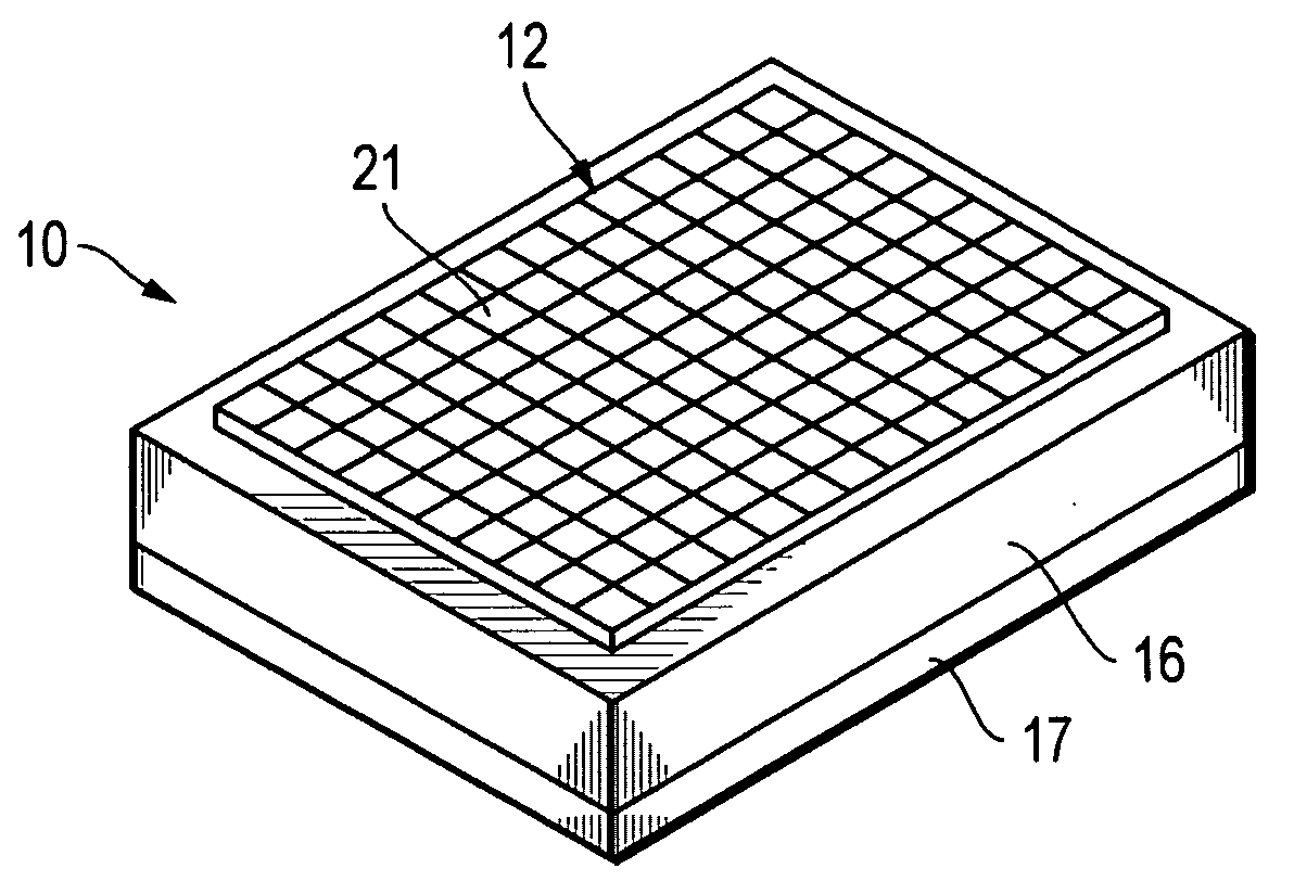
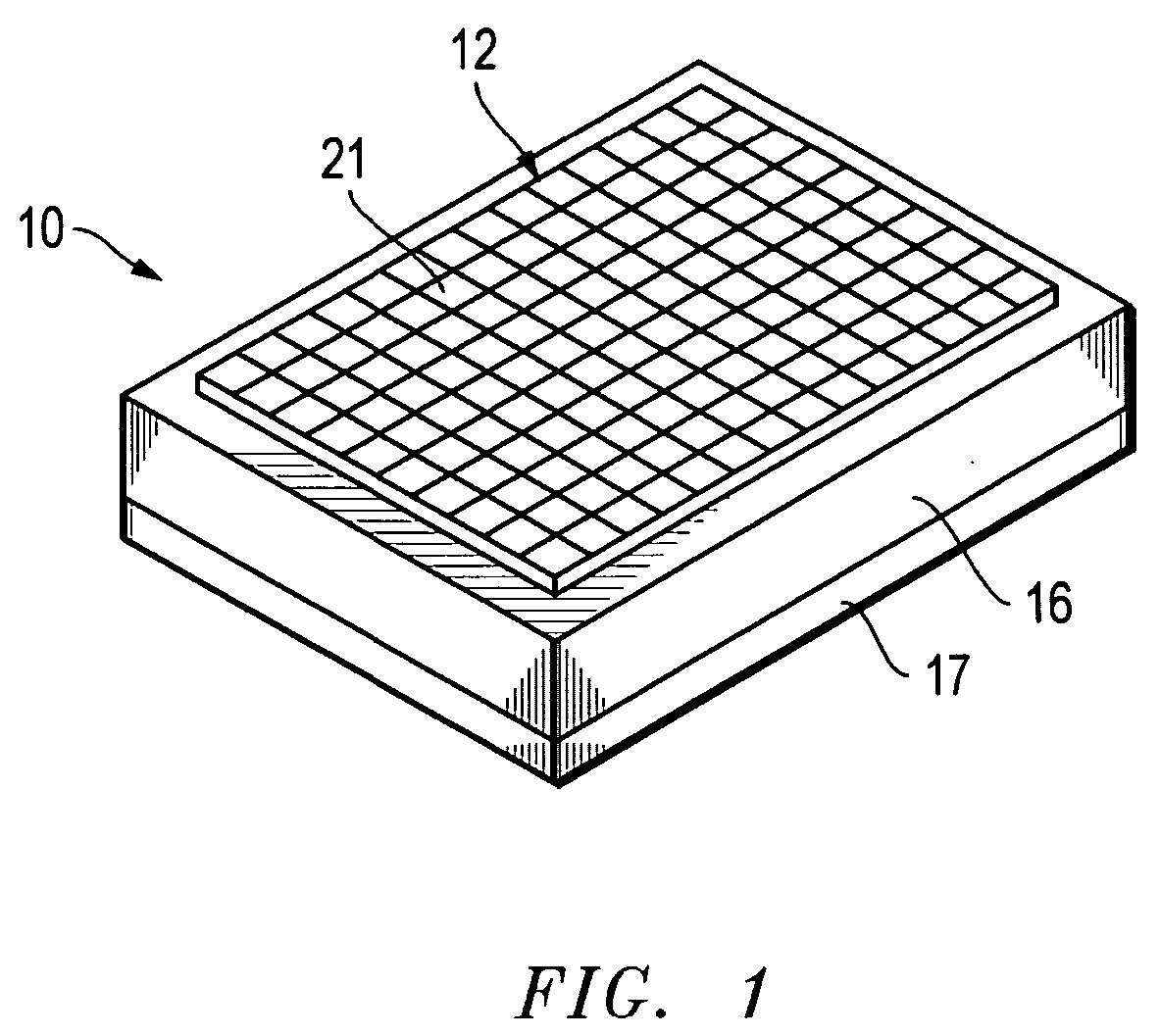
[0023]FIG. 1 is a diagrammatic perspective view of an infrared detector 10 which may be used according to one embodiment of the disclosed systems and methods to sense thermal energy and output electrical signals representative of a two-dimensional image of that sensed thermal energy. In this embodiment, the infrared detector 10 includes a focal plane array (FPA) 12 disposed on a substrate 16. The substrate 16 includes an integrated circuit of a type which is commonly known as a read out integrated circuit (ROIC). The ROIC integrates the thermally induced electrical signals from each detector element 21 in the focal plane array 12 and multiplexes the signals off the array with the appropriate signal conditioning and processing.

[0024] As shown in FIG. 1, an optional thermal element 17 (e.g., active heat sink) may be provided on the side of the substrate 16 opposite from the focal plane array 12, in order to serve as a form of controlled heat sink which may be used, for example, to ma...


PUM


Abstract

Methods for making optically blind reference pixels and systems employing the same. The reference pixels may be configured to be identical to, or substantially identical to, the active detector elements of a focal plane array assembly. The reference pixels may be configured to use the same relatively longer thermal isolation legs as the active detector pixels of the focal plane, thus eliminating joule heating differences. An optically blocking structure may be placed in close proximity directly over the reference pixels.

Description

[0001] This patent application claims priority to copending U.S. Provisional patent application Ser. No. 60 / 635,398, filed Dec. 10, 2004, and entitled “OPTICALLY BLOCKED REFERENCE PIXELS FOR FOCAL PLANE ARRAYS” by Schimert et al., the entire disclosure of which is incorporated herein by reference.BACKGROUND OF THE INVENTION [0002] 1. Field of the Invention [0003] This invention relates generally to focal plane arrays, and more particularly to reference pixels for focal plane arrays [0004] 2. Description of the Related Art [0005] Microelectromechanical systems (MEMS) are integrated micro devices or systems combining electrical and mechanical components. Some MEMS devices may be fabricated using standard integrated circuit batch processing techniques and have a variety of applications including sensing controlling and actuating on a micro scale. MEMS devices may function individually or in arrays to generate effects on a macro scale. [0006] Certain MEMS devices require a vacuum enviro...

Claims


Application Information

Patent Timeline
IPC IPC(8): H01J40/14
CPCH01L27/14618H01L27/14623H01L27/1463H01L27/14634H01L27/1465H01L24/05H01L2224/05568H01L2224/05644H01L2224/05666H01L2224/05669H01L2224/16H01L2924/1461H01L2924/00014
Inventor SCHIMERT, THOMAS R.SYLLAIOS, ATHANASIOS J.GOOCH, ROLAND W.MCCARDEL, WILLIAM L.
Owner DRS NETWORK & IMAGING SYST
Why Eureka
Try Eureka