A slag fine grinding system

A fine powder and slag technology, applied in mixers, dissolving, chemical instruments and methods, etc., can solve the problems of restricting the increase of slag content, large average particle size of slag, and low fine powder content, etc. A number of performance improvements and the effect of increasing the specific surface area

Active Publication Date: 2019-08-09
海南檀溪新型材料有限公司
View PDF7 Cites 0 Cited by
  • Summary
  • Abstract
  • Description
  • Claims
  • Application Information

AI Technical Summary

Problems solved by technology

[0003] However, the traditional P·S production method is to mix and grind cement clinker and slag in a grinding equipment (mainly a ball mill). Due to the large difference in grindability between clinker and slag, the slag in the obtained cement The average particle size is too large, the content of fine powder is low, and its potential activity cannot be effectively exerted, which affects the early strength and other properties of cement, and also restricts the increase of slag content.

Method used


Image

  • A slag fine grinding system
  • A slag fine grinding system
  • A slag fine grinding system

Examples


Embodiment 1

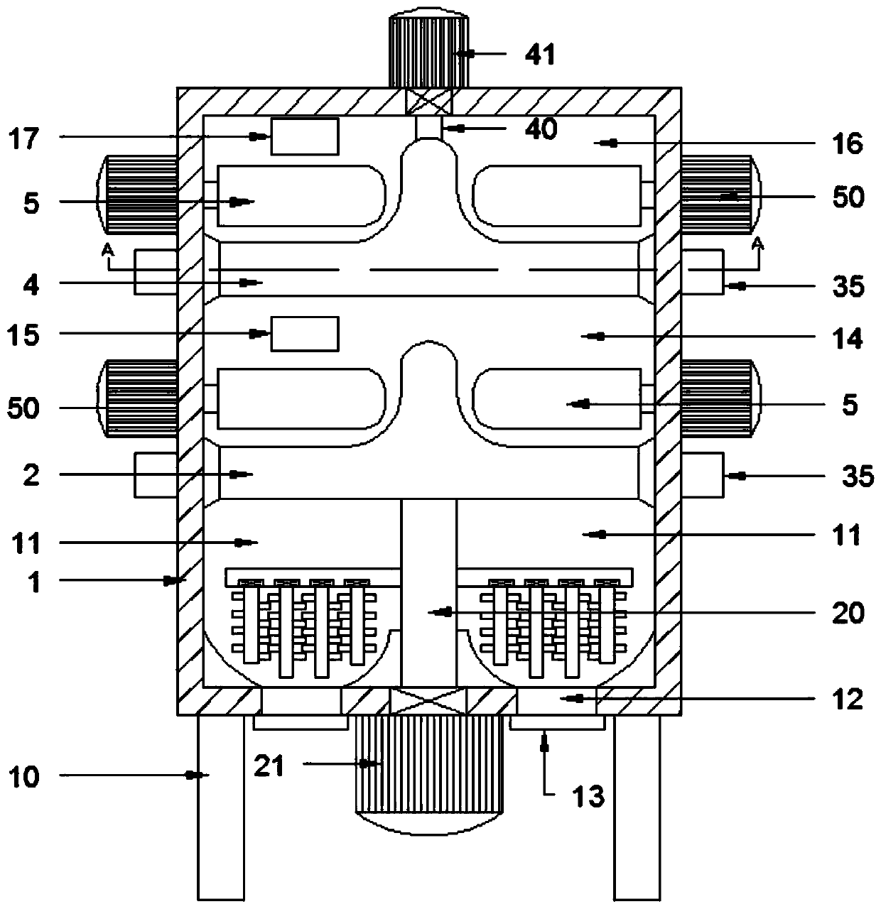
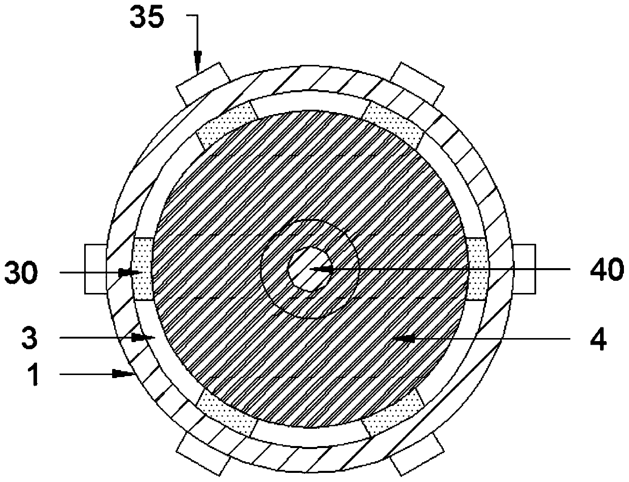
[0023] see Figure 1~5 , in an embodiment of the present invention, a slag fine grinding system includes a grinding box 1, the bottom of the grinding box 1 is supported on the ground by a plurality of support columns 10, and the inside of the grinding box 1 is from top to The clinker grinding table 4 and the slag grinding table 2 are provided in sequence at the bottom, and the clinker grinding table 4 and the slag grinding table 2 divide the inside of the grinding box 1 from top to bottom into a cement clinker rolling chamber 16, a slag rolling chamber 14 and a stirring chamber. chamber 11, the rear panels of the slag rolling chamber 14 and the cement clinker rolling chamber 16 are respectively provided with a slag feed port 15 and a clinker feed port 17, and the inner bottom of the mixing chamber 11 is provided with a plurality of A stirring discharge port 12 for discharging, a material valve cover 13 is installed on the outer opening of the stirring discharge port 12, the cl...

Embodiment 2

[0029] The difference between this embodiment and embodiment 1 is:

[0030] A frustum-shaped coupling rotating base 22 is fixed around the bottom rod wall of the interlocking rotating shaft 20 , and a downwardly inclined material guide slope 26 is fixed around the bottom surface of the mixing chamber 11 .

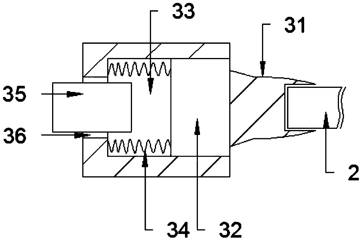
[0031] The electromagnetic opening and closing mechanism includes a plugging plate 31, a telescopic block 32, a telescopic groove 33, a telescopic spring 34 and an electromagnet (35). The side wall of the clinker grinding plate 4 is clamped and sealed with each other. The outer end of the blocking insert 31 is fixed on the telescopic block 32, and the telescopic block 32 slides and is stuck in the telescopic groove 33. In the inside of the left and right side walls of the grinding box 1, the telescopic block 32 and the inner wall of the telescopic groove 33 are laterally fixed with a plurality of telescopic springs 34 with elastic force toward the inside of the mixing chamb...


PUM

PropertyMeasurementUnit
specific surface areaaaaaaaaaaa

Abstract

The invention discloses a slag fine grinding system, which comprises a grinding box, the bottom of the grinding box is supported on the ground by a plurality of support columns, and clinker grinding discs are sequentially arranged in the grinding box from top to bottom And the slag grinding table, the clinker grinding table and the slag grinding table divide the inside of the grinding box into cement clinker rolling room, slag rolling room and mixing room from top to bottom, and the clinker grinding table is suspended on the The inner top of the grinding box, the slag grinding table is supported inside the grinding box by a linkage drive device, a plurality of rolling rollers are arranged horizontally on the top surface of the slag grinding table and clinker grinding table, and the mixing chamber is equipped with There is a stirring mechanism for mixing cement clinker and slag; the present invention solves the problem of large difference in grindability between slag and cement clinker in the past by using separate chambers for grinding into powder and then stirring and mixing. The high specific surface area and fineness of slag and clinker after grinding are greatly improved.

Description

technical field [0001] The invention relates to a grinding and stirring device system, in particular to a slag fine grinding system. Background technique [0002] Slag is a by-product of blast furnace ironmaking in steel plants. After water quenching and quenching, it is in the form of light gray glass crystal particles and belongs to industrial waste slag materials. Slag has been used as cement admixture in my country for more than 40 years, but most of them are ground slag and cement clinker together, which is an extensive application. Slag with "potential hydraulicity" is the best mixing material for cement production. Ordinary Portland cement (P·O) and slag Portland cement (P·S) can be produced with slag as a mixed material. The national standard for general Portland cement stipulates that the amount of slag in P·O should not exceed 15%, while The amount of slag in P·S can be 20% to 70%. Therefore, P·S is more meaningful to maximize the use of slag and reduce the cost of...

Claims


Application Information

Patent Timeline
Patent Type & Authority Patents(China)
IPC IPC(8): B02C15/00B02C23/00B01F7/18
CPCB02C15/00B02C15/003B02C15/004B02C23/00B01F27/90
Inventor 符德智孙国晶
Owner 海南檀溪新型材料有限公司
Why Eureka
Try Eureka