Method of automatically adjusting position of lens, lens position adjusting device and projector

A technology for automatic adjustment and adjustment of devices, which is applied to projection devices, installations, instruments, etc., and can solve problems such as inaccurate focus

Inactive Publication Date: 2019-04-16
CHENGDU XGIMI TECH CO LTD
View PDF8 Cites 7 Cited by
  • Summary
  • Abstract
  • Description
  • Claims
  • Application Information

AI Technical Summary

Problems solved by technology

[0004] Therefore, there is a need for a method that can solve the problem of inaccurate focus due to the backlash phenomenon of the drive gear

Method used


Image

  • Method of automatically adjusting position of lens, lens position adjusting device and projector

Examples


Embodiment Construction

[0028] In order to enable those skilled in the art to better understand the technical solutions of the present invention, the present invention will be further described in detail below in conjunction with the accompanying drawings and specific embodiments.

[0029] The invention provides a lens position adjustment device. The lens position adjustment device includes a drive module, a displacement measurement module, a sharpness calculation module, a recording module and a control module.

[0030] The driving module is used to move the lens;

[0031] The displacement measurement module is used to measure the displacement of the lens to a reference position;

[0032] The sharpness calculation module is used to calculate the sharpness of the lens imaging;

[0033] The recording module is used to record the correspondence between the definition and the displacement;

[0034] The control module is used for

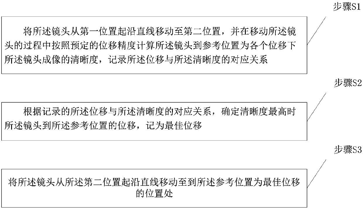
[0035] controlling the drive module to move the lens from the first p...


PUM


Abstract

The invention relates to an optical device and a focusing method thereof, in particular to a method of automatically adjusting the position of a lens, a lens position adjusting device and a projector.The method comprises steps: S1, the lens is moved to a second position from a first position along a straight line, the lens imaging clarity under each displacement when the lens moves to a referenceposition is calculated according to a predetermined displacement accuracy in the process of moving the lens, and the corresponding relationship between the displacement and the clarity is recorded; S2, according to the recorded corresponding relationship between the displacement and the clarity, a displacement to the reference position by the lens in the case of the highest clarity is determinedand is recorded as the best displacement; and S3, the lens is moved to the position with the reference position as the best displacement from the second position along a straight line. Thus, the problem of inaccurate focusing caused by empty return of a gear of a driving device can be solved.

Description

technical field [0001] The invention relates to an optical device and a focusing method thereof, in particular to a method for automatically adjusting the position of a lens, a device for adjusting the position of the lens and a projector. Background technique [0002] In existing projector focusing devices, a sensor is placed at a fixed position as a fixed focusing reference point. The control board drives the motor to rotate to move the lens. When the lens moves, the number of steps the motor rotates will be fed back to the control board. Usually, in order to determine whether the lens shows the highest definition on the object surface, it is necessary to make the lens pass through and exceed the best imaging point. At this time, the control board records the number of steps of the motor rotation at the time of the best imaging, combined with the current position of the motor rotation. The number of steps calculates how many steps the camera should be rotated. [0003] ...

Claims


Application Information

Patent Timeline
Patent Type & Authority Applications(China)
IPC IPC(8): G02B7/38G03B21/14
CPCG02B7/38G03B21/142
Inventor 钟波肖适王鑫尹蕾王皓兰
Owner CHENGDU XGIMI TECH CO LTD
Why Eureka
Try Eureka