High-frequency isolation conversion energy storage system

A high-frequency isolation and energy storage system technology, applied in the field of high-frequency isolation and conversion energy storage systems, can solve the problems of inability to convert energy, large cost or volume, and no effective method to limit the power of energy storage devices, so as to reduce failures The effect of current

Pending Publication Date: 2019-04-23
SHENZHEN YINGFEIYUAN TECH CO LTD
View PDF7 Cites 3 Cited by
  • Summary
  • Abstract
  • Description
  • Claims
  • Application Information

AI Technical Summary

Problems solved by technology

The traditional solution is to add an isolation transformer on the AC side of the inverter system. Due to the low frequency, the electric energy passing through the transformer is still very large. However, in the DC bus, there is no effective way to limit the electric energy released by the energy storage device.
[0005] For charging and discharging applications with impact characteristics, there is a limit to directly adopting one energy storage method
For example, as a high-current charging for energy recovery, the cost or volume of directly using a battery is relatively large. The solution is to use a combination of different energy storage methods. High-rate short-term energy storage uses super capacitors or large-rate energy storage batteries. Energy storage is combined with general lithium-ion batteries, which cannot be flexibly converted into energy

Method used


Image

  • High-frequency isolation conversion energy storage system
  • High-frequency isolation conversion energy storage system
  • High-frequency isolation conversion energy storage system

Examples


Embodiment approach 1

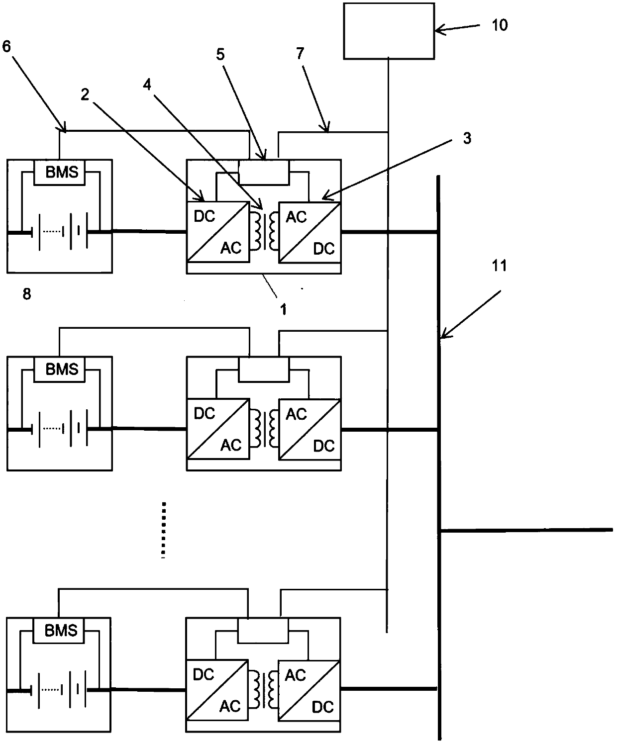
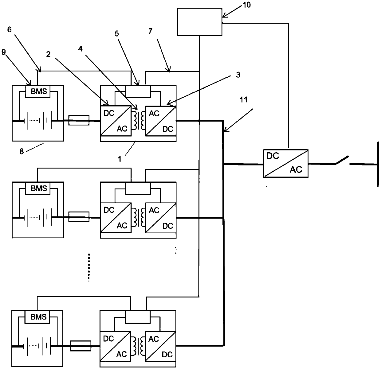
[0037] as attached figure 2 , a high-frequency isolated bidirectional conversion energy storage system, including high-frequency isolated conversion bidirectional DC / DC conversion device, DC bus, battery pack, bidirectional inverter equipment (PCS).

[0038] The high-frequency isolation bidirectional conversion energy storage system includes multiple groups of battery packs, and multiple groups of high-frequency isolation bidirectional conversion devices connected to the batteries, which are connected to the DC bus. The bidirectional inverter device connects the DC bus and the AC grid.

[0039] The energy of the multiple groups of batteries is discharged to the grid through bidirectional DC / DC conversion and bidirectional DC / AC conversion, and at the same time, the grid charges the battery groups through the conversion device.

[0040] This embodiment is applied to energy exchange between the battery and the grid.

Embodiment approach 2

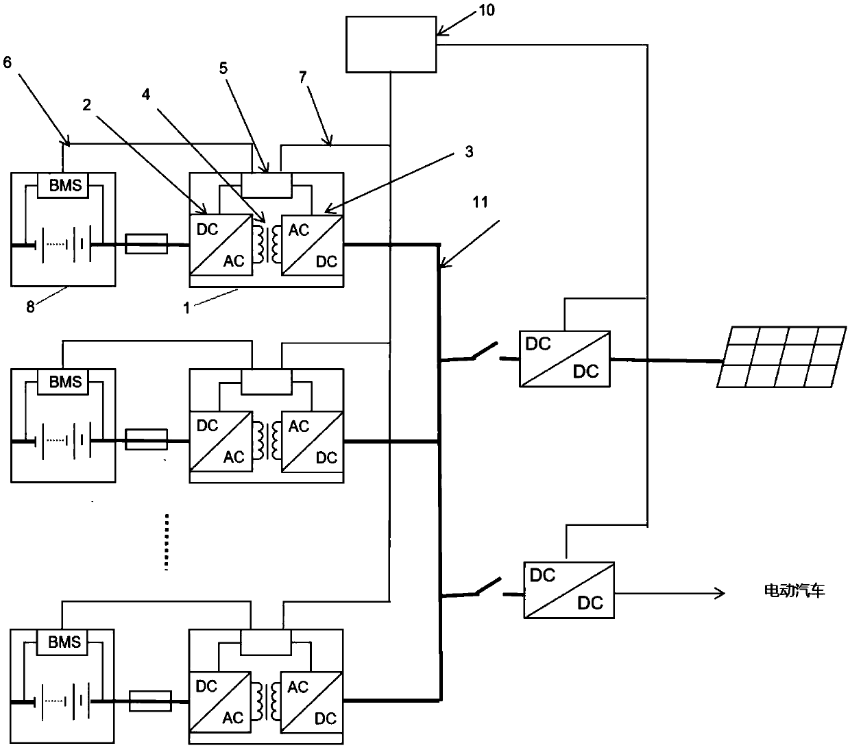
[0042] as attached image 3 , The high-frequency isolated bidirectional conversion energy storage system connects multiple battery packs to the DC bus, and the DC bus is connected to the photovoltaic array through the maximum power tracking conversion device MPPT. At the same time, the DC bus is connected to the DC / DC DC charging system to charge the electric vehicle.

[0043] The above embodiment is an off-grid photovoltaic energy storage charging system. Electric energy comes from the photovoltaic array, supplies power to the DC bus through maximum power tracking, and supplies power to the DC charging equipment through the bus, and excess electric energy is stored in the battery pack through the energy storage system. When there is no solar power, the battery pack discharges, providing power to the bus.

[0044] The system is connected to different battery packs through a plurality of bidirectional conversion devices, preferably, the retired battery packs are connected, and...


PUM


Abstract

The invention discloses a high-frequency isolation conversion energy storage system, which comprises high-frequency isolation conversion two-way DC / DC conversion devices and a direct current bus, wherein a first connecting point of each two-way DC / DC device is connected with an energy storage device; a second connecting point is connected to the direct current bus; through the two-way DC / DC devices, electric energy in the energy storage devices can be subjected to two-way alternating with the direct current bus through high-frequency isolation conversion. A plurality of energy storage devicesare isolated from the high-frequency isolation transformers of the two-way conversion devices subjected to high-frequency isolation from the direct current bus; the electric energy passing through a transformer is limited, so that the fault current of the direct current bus is reduced; the goal of safe protection is achieved; the plurality of groups of energy storage devices are connected with thebus through respectively independent two-way isolation conversion devices; the differences among different energy storage devices cannot generate mutual influence; the energy storage devices with different properties can even be used in a combined way.

Description

technical field [0001] The invention relates to a high-frequency isolated energy storage system, in particular to a high-frequency isolated and transformed energy storage system. Background technique [0002] When multiple energy storage devices are connected to other systems, due to the different voltages of a single energy storage device, the voltages of internal units are unbalanced, resulting in multiple energy storage devices that cannot be directly connected in parallel, or there are hidden dangers in long-term use in parallel. Especially lithium-ion batteries, when forming a large-scale energy storage system, there are too many series and parallel batteries, and the imbalance of batteries has become a technical bottleneck for its large-scale energy storage use. [0003] What is more prominent is that when retired batteries are used as energy storage, the differences between different battery packs are greater, and they cannot be directly used in parallel, and their ch...

Claims


Application Information

Patent Timeline
Patent Type & Authority Applications(China)
IPC IPC(8): H02J7/34H02J1/10
CPCH02J1/102H02J7/34
Inventor 谢国辉柳树渡王渭渭岳兴
Owner SHENZHEN YINGFEIYUAN TECH CO LTD
Why Eureka
Try Eureka