DC power grid topology based on coupling transformer under high impedance grounding and fault positioning method thereof

A high-impedance grounding, DC power grid technology, applied in the direction of fault location, fault detection according to conductor type, information technology support system, etc., can solve problems such as small fault current, failure to locate faults through current, small fault current in fault loops, etc.

Inactive Publication Date: 2019-10-11
XJ ELECTRIC +1
View PDF13 Cites 0 Cited by
  • Summary
  • Abstract
  • Description
  • Claims
  • Application Information

AI Technical Summary

Problems solved by technology

[0004] The purpose of the present invention is to provide a fault location method based on the high-impedance grounded DC power grid topology of the connected transformer, which is used to solve the problem of fault current poles in the fault loop when the DC power grid topology based on the connected transformer is high-impedance grounded. Small, unable to realize the problem of fault location through current
At the same time, the present invention provides a DC power grid topology based on the high-impedance grounding of the connected transformer, which is used to solve the problem that the fault current in the fault loop is extremely small when the DC power grid topology based on the connected transformer is high-impedance grounded. The problem of fault location

Method used


Image

  • DC power grid topology based on coupling transformer under high impedance grounding and fault positioning method thereof
  • DC power grid topology based on coupling transformer under high impedance grounding and fault positioning method thereof
  • DC power grid topology based on coupling transformer under high impedance grounding and fault positioning method thereof

Examples


Embodiment Construction

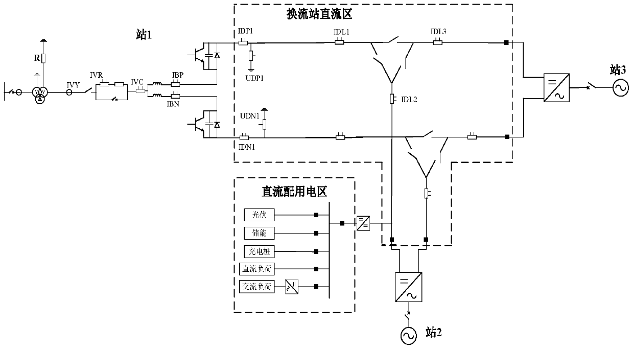
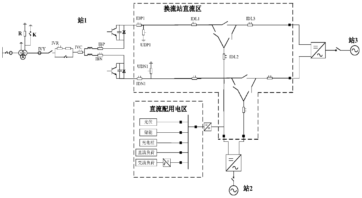
[0024] Example of DC power grid topology based on connected transformer via high-impedance grounding:

[0025] This embodiment provides a DC power grid topology based on connected transformers with high-impedance grounding, including a DC line network and at least two converter stations, where three converter stations are used as an example, as figure 2 As shown, they are station 1, station 2 and station 3 respectively. The DC power grid topology can only include converter stations, and does not involve other distributed power generation and power consumption parts. Then, the DC power grid topology is a DC power transmission system. Of course, in this DC power grid topology, in addition to the converter station In addition, other distributed power generation parts and power consumption parts can also be involved. Then, the DC power grid topology is a DC power grid system integrating power transmission, power distribution and power consumption. In this embodiment, the DC grid...


PUM


Abstract

The invention relates to a DC power grid topology based on a coupling transformer under high impedance grounding, and a fault positioning method thereof. The positioning method comprises the followingsteps: firstly detecting a DC voltage signal of a DC line through a way of detecting the voltage signal, initially judging whether the fault occurs; after judging that the fault occurs, controlling to short-circuit a high-impedance grounding line arranged between the neutral point of the coupling transformer and the ground, in this case, the fault current can produce in the DC line since the highimpedance arranged between the neutral point of the coupling transformer and the ground is short-circuited; and then detecting the fault positioning according to the fault current. Therefore. The fault positioning method is suitable for the DC power grid topology based on the coupling transformer high-impedance grounding, the fault positioning can be realized, and then the fault overhauling can be performed according to the fault location, and a fault positioning demand of the DC power grid topology based on coupling transformer high impedance grounding can be satisfied; furthermore, the fault positioning method is simple and practical, easy for engineering field implementation, and capable of improving the reliability of the DC power grid.

Description

technical field [0001] The invention relates to a direct current power grid topology and a fault location method based on a high-impedance grounding connection transformer. Background technique [0002] The DC distribution network can alleviate the contradiction between the limited corridors of the AC grid site and the high load density, and has the advantages of better receiving DC loads, an obvious trend of end-user load DC, better high-quality electricity demand, and easy distributed energy and energy storage. Therefore, the DC distribution network will be the main development direction of the distribution network. [0003] As a new power distribution technology, DC distribution network is in the initial stage of development, such as figure 1 As shown, the connected transformer (connected transformer) is grounded through a high resistance (resistance R with a very large resistance) is a typical topology of the DC distribution network, that is, the neutral point of the co...

Claims


Application Information

Patent Timeline
Patent Type & Authority Applications(China)
IPC IPC(8): G01R31/08
CPCG01R31/086Y04S10/52
Inventor 吴庆范田培涛陈大鹏李传西周晓风崔晨范雪峰王秋开宋延涛岳笑歌张成功李志阳雷玉磊付艳王长久王胜孙攀磊陈朋黄金海戴国安曹森郝俊芳刘星郭宏光
Owner XJ ELECTRIC
Why Eureka
Try Eureka