A flame thermal shock test observation device and observation method

An impact test and observation device technology, applied in the field of test instruments and experimental mechanics, can solve the problems of inaccurate testing of the specific time and growth rate of cracks, unfavorable thermal shock process, and large error in results, so as to achieve convenient comparison tests and guarantee Uniformity, the effect of avoiding errors

Active Publication Date: 2020-06-30
INST OF MECHANICS CHINESE ACAD OF SCI +1
View PDF9 Cites 0 Cited by
  • Summary
  • Abstract
  • Description
  • Claims
  • Application Information

AI Technical Summary

Problems solved by technology

[0005] (1) The water quenching shock thermal shock test is a compromise method. Although it is convenient, it cannot truly reflect the thermal shock thermal shock process of the material. In fact, high-temperature materials are more often subjected to thermal shock thermal shock. Therefore, the water quenching thermal shock test cannot accurately test the specific time and growth rate of the cracks in the material when it is subjected to thermal shock, which is not conducive to accurately testing the properties of the material;
[0006] (2) In the thermal shock test, in order to describe the thermal shock process of the sample, it is necessary to accurately know the heat exchange of the sample in the test, and because the water itself is heated and evaporates easily, during the water quenching process, the water and the test sample It is difficult to calculate the heat transfer rate of the sample, which is not conducive to accurately describe the thermal shock process of the sample;
[0007] (3) When conducting thermal shock tests, it is usually necessary to measure multiple sets of data and to conduct comparative tests, but the existing scheme is difficult to ensure the uniformity of test conditions during multiple tests, resulting in large errors in test results

Method used


Image

  • A flame thermal shock test observation device and observation method
  • A flame thermal shock test observation device and observation method
  • A flame thermal shock test observation device and observation method

Examples


Embodiment Construction

[0042] The implementation mode of the present invention is illustrated by specific specific examples below, and those who are familiar with this technology can easily understand other advantages and effects of the present invention from the contents disclosed in this description. Obviously, the described embodiments are a part of the present invention. , but not all examples. Based on the embodiments of the present invention, all other embodiments obtained by persons of ordinary skill in the art without making creative efforts belong to the protection scope of the present invention.

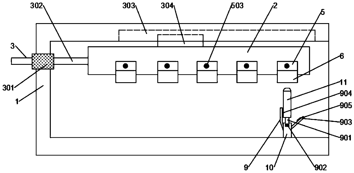
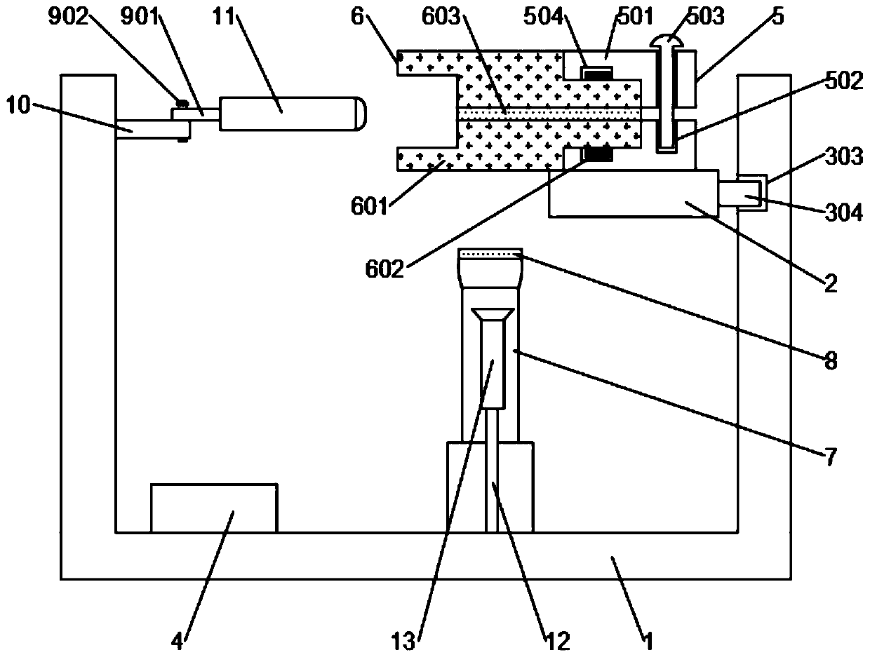
[0043] Such as figure 1 and figure 2 As shown, the present invention provides a flame thermal shock test observation device, comprising a test frame 1, the top of the test frame 1 is provided with a workbench 2, the end of the workbench 2 is connected with a multi-stage drive structure 3, the test frame 1 A controller 4 for controlling the multi-gear drive structure 3 is installed at the botto...


PUM


Abstract

The invention discloses a flame thermal shock test observation device and method. The device includes a test rack, wherein the top of the test rack is provided with a work stand, an end portion of thework stand is connected with a multi-shift driving structure, the top of the work stand is provided with multiple uniformly-distributed first clamps, the first clamps are internally clamped with second transparent clamps, front ends of the second transparent clamps stretch out of the work stand, high-speed cameras fixed on the test rack are arranged just below the second transparent clamps, the side of the work stand is provided with a telescopic support, and an inner end of the telescopic support is connected with an aerobic acetylene flame spray gun through a shifting structure. The deviceis advantaged in that observation is more convenient and accurate, the time and the growth rate of cracks when a material is subjected to thermal shock can be accurately calculated, moreover, measurement of multiple sets of data and comparative tests can be more conveniently performed, uniformity of test conditions in many tests is guaranteed, and errors in test results can be avoided.

Description

technical field [0001] The embodiments of the present invention relate to the technical field of test instruments and experimental mechanics, and in particular to an observation device and an observation method for a flame thermal shock test. Background technique [0002] With the development of aerospace technology, the service environment of materials has become very harsh, and there is an urgent need for high-temperature materials with excellent high-temperature performance. Ceramics have become the most promising candidate materials for aerospace due to their high melting point, corrosion resistance, wear resistance and high temperature chemical stability. The thermal shock resistance of materials has become one of the important criteria for selecting and designing materials. [0003] The traditional thermal shock test is divided into cold shock and thermal shock. The former is achieved by heating the sample to a certain temperature and throwing it into a cold shock med...

Claims


Application Information

Patent Timeline
Patent Type & Authority Patents(China)
IPC IPC(8): G01N3/60G01N3/02G01N3/06
CPCG01N3/02G01N3/068G01N3/60G01N2203/0057G01N2203/0064G01N2203/0066G01N2203/0647
Inventor 邵颖峰武小峰郇勇宋凡
Owner INST OF MECHANICS CHINESE ACAD OF SCI
Why Eureka
Try Eureka