Small adjustable 5G signal transmitting tower
An adjustable technology for transmission towers, applied in the field of signal transmission towers, can solve the problems of inability to fine-tune the height, single structure of signal towers, etc., and achieve the effect of enhanced stability and stable support
- Summary
- Abstract
- Description
- Claims
- Application Information
AI Technical Summary
Problems solved by technology
Method used
Image

Examples
specific Embodiment approach 1
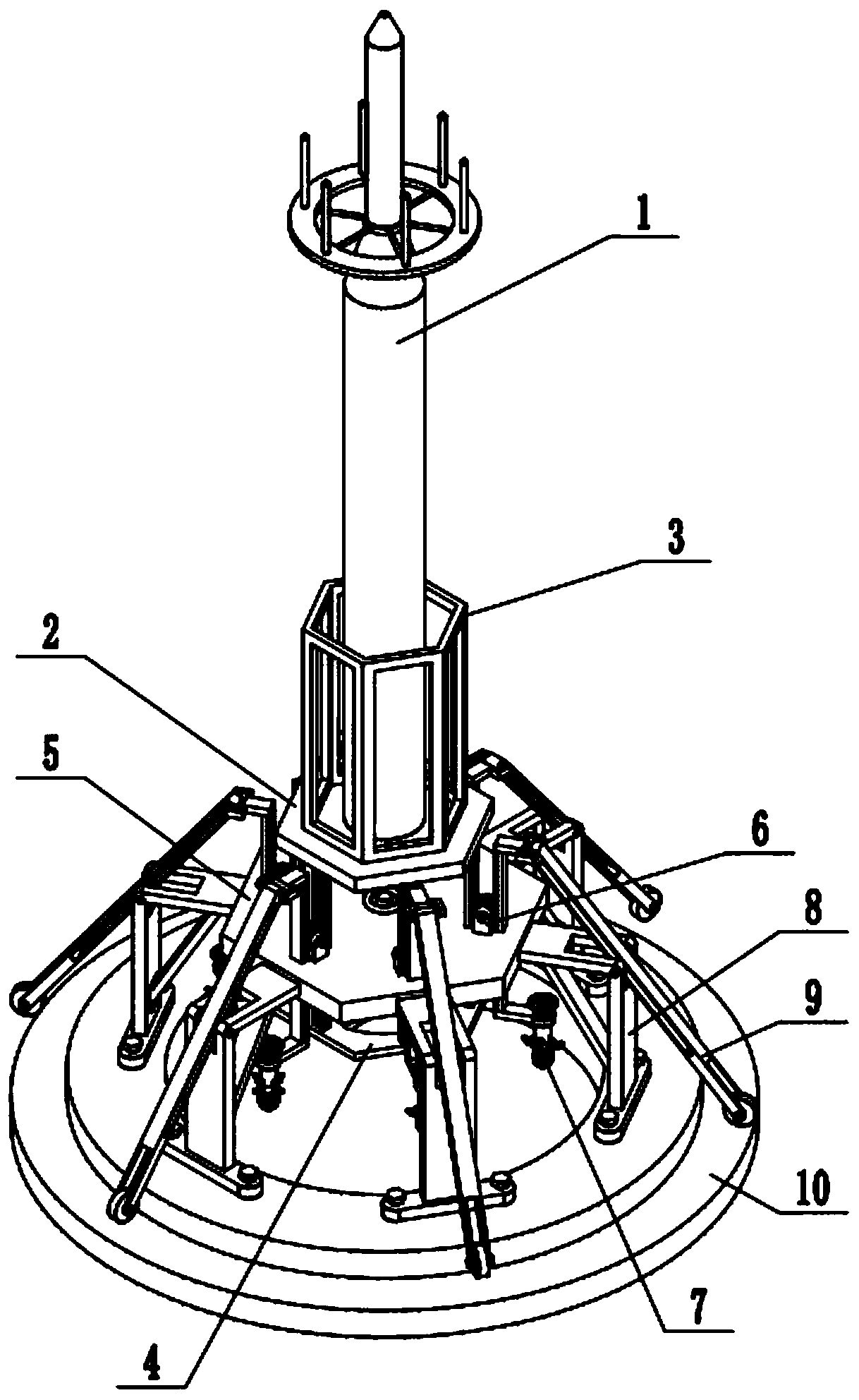
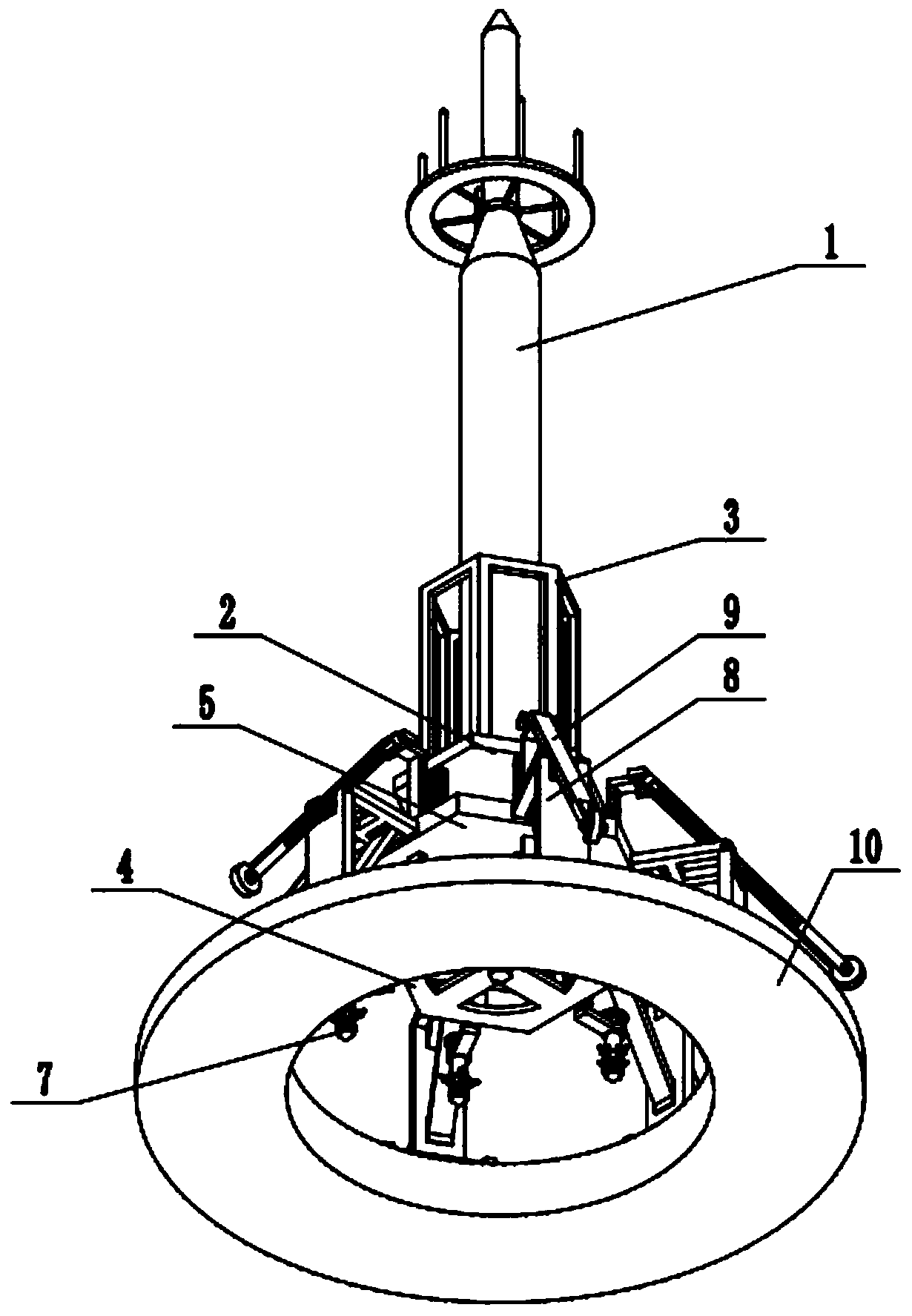
[0030] Such as Figure 1-10 As shown, a small adjustable 5G signal transmission tower includes a transmission tower body 1, a lifting base 2, a guardrail 3, a base height adjustment mechanism 4, a fixed base 5, a gear mechanism 6, an auxiliary positioning mechanism 7, a fixed The support mechanism 8, the movable support mechanism 9 and the buried base 10, the launch tower body 1 and the guardrail 3 are all fixedly connected on the lifting base 2; the guardrail 3 is sleeved on the outside of the launch tower body 1 The lower end of the lifting base 2 is fixedly connected to the upper end of the base height adjustment mechanism 4, and the lower end of the base height adjustment mechanism 4 is connected to the fixed base 5; the outer side of the fixed base 5 is uniformly fixedly connected to six fixed The upper end of the bracket mechanism 8 and the lower ends of the six fixed bracket mechanisms 8 are evenly and fixedly connected to the top surface of the buried base 10; On the ...
specific Embodiment approach 2
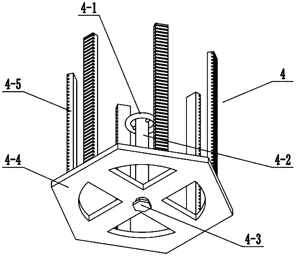
[0032] Such as Figure 1-10 As shown, the base height adjustment mechanism 4 includes a height adjustment swivel 4-1, a screw 4-2, a limit block 4-3, a lifting bracket 4-4 and a transmission rack 4-5; the height The adjustment swivel 4-1 is fixedly connected to the top of the lead screw 4-2, the upper end of the lead screw 4-2 is connected to the center of the fixed base 5 through a bearing with seat for rotation fit, and the height adjustment swivel 4-1 is located on the fixed base 5; the bottom end of the leading screw 4-2 is fixedly connected to the limit block 4-3; the center of the lifting bracket 4-4 is threaded on the leading screw 4-2, and the lifting bracket 4-4 Located between the fixed base 5 and the limit block 4-3; the transmission rack 4-5 is provided with six, and the lower ends of the six transmission racks 4-5 are uniformly surrounded and fixedly connected to the top of the lifting bracket 4-4 On the outer side of the surface, the middle ends of the six trans...
specific Embodiment approach 3
[0033] Such as Figure 1-10 As shown, two axial retaining rings are fixedly connected to the screw 4-2, and the two axial retaining rings are slidingly matched with the upper and lower surfaces of the fixed base 5 respectively. The axial stop ring on the screw 4-2 can act as an axial limit to prevent the screw 4-2 from breaking away from the fixed base 5.
PUM
 Abstract
Description
Claims
Application Information
 - R&D Engineer
- R&D Manager
- IP Professional
- Industry Leading Data Capabilities
- Powerful AI technology
- Patent DNA Extraction
Browse by: Latest US Patents, China's latest patents, Technical Efficacy Thesaurus, Application Domain, Technology Topic.
© 2024 PatSnap. All rights reserved.Legal|Privacy policy|Modern Slavery Act Transparency Statement|Sitemap