
Heating device for relaxer and relaxer

A technology of heating device and heating element, applied in the field of fitness equipment, can solve the problems of single function of muscle relaxer and only output vibration.

Pending Publication Date: 2019-06-28
SHENZHEN SILK ROAD E COMMERCE TECH CO LTD
View PDF5 Cites 2 Cited by
  • Summary
  • Abstract
  • Description
  • Claims
  • Application Information

AI Technical Summary

Problems solved by technology

[0005] In view of the above deficiencies in the prior art, the object of the present invention is to provide a heating device and a relaxer for a relaxer, aiming to solve the problem that the existing muscle relaxers have a single function and can only output vibrations

Method used


Image

  • Heating device for relaxer and relaxer
  • Heating device for relaxer and relaxer
  • Heating device for relaxer and relaxer

Examples


Embodiment Construction

[0026] The present invention provides a heating device and a relaxer for a relaxer. In order to make the purpose, technical solution and effect of the present invention clearer and clearer, the present invention will be further described in detail with reference to the accompanying drawings and examples. It should be understood that the specific embodiments described here are only used to explain the present invention, but not to limit the present invention.

[0027] The specific implementation of the present invention is to facilitate a more detailed description of the concept of the present invention, the technical problem to be solved, the technical features constituting the technical solution, and the technical effects brought by it. It should be noted that the explanation of these embodiments does not constitute a limitation on the protection scope of the present invention. In addition, the technical features involved in the embodiments described below can be combined with e...


PUM


Abstract

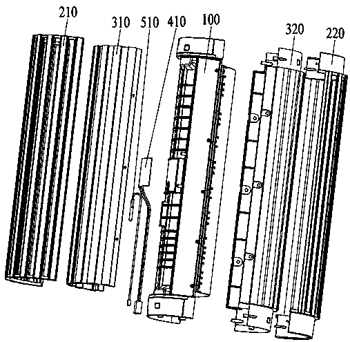
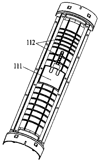
The invention discloses a heating device for a relaxer and the relaxer. The heating device for the relaxer comprises an inner casing for transmitting vibration and an outer casing for transmitting vibration and conducting heat, and a heating member is disposed between the outer casing and the inner casing. The heating device for the relaxer can not only output the vibration through the inner casing and the outer casing, but also output heat through the heating member and the outer casing, and the relaxer has a heat applying function, thereby solving the existing problem that a current muscle relaxer has a single function and can only output vibration.

Description

Technical field [0001] The invention relates to the technical field of fitness equipment, in particular to a heat generating device used for a relaxer and a relaxer. Background technique [0002] A muscle relaxer is a commonly used portable instrument for relaxing muscles. The structure of a common muscle relaxer includes a foam shaft and a vibration component. The foam shaft is provided with a through cavity. The vibration component includes a housing, a motor, The pendulum and the rotating bearing, wherein the shell is detachably installed in the through cavity, the motor and the pendulum are installed in the shell, and the pendulum is connected with the motor output shaft, and the rotating bearing is sleeved on the end of the motor output shaft. When the motor is running, the pendulum is driven by the output shaft of the motor to rotate, and the vibration is output through the housing, and the vibration frequency is controlled by the motor. [0003] The disadvantage of the exis...

Claims


Application Information

Patent Timeline
Patent Type & Authority Applications(China)
IPC IPC(8): A61F7/00A61H23/02H05B3/34H05B3/02
CPCH05B3/02H05B3/34A61F7/00A61H23/02A61H15/00
Inventor 周志华金泉贝
Owner SHENZHEN SILK ROAD E COMMERCE TECH CO LTD
Learn More