LED lamp optical system capable of generating water wave 3D fluctuation effect

A technology of LED lamps and optical systems, applied in the direction of light source, light source fixation, lighting device components, etc., can solve the problems of increasing the length of lamps, insufficient disclosure of optical principles, etc.

Pending Publication Date: 2019-08-09
GUANGZHOU DASEN LIGHTING ELECTRONICS
View PDF6 Cites 0 Cited by
  • Summary
  • Abstract
  • Description
  • Claims
  • Application Information

AI Technical Summary

Problems solved by technology

It can be seen from the above that the "1-point light source effect" is achieved by the ratio of the length and width of the LED light source to the focal length of the swinging light-transmitting sheet and the fixed light-transmitting sheet being 1:30, which is obviously too large. Seriously increased the length of the lamp; in addition, the light directly passes through the swinging light-transmitting sheet and the fixed light-transmitting sheet, and the light intensity difference between the bright and dark areas is not explained, that is, it realizes "3-each image The technical parameters, optical principles, and actual effects of "composed of regions with large differences in light intensity" are insufficiently disclosed

Method used


Image

  • LED lamp optical system capable of generating water wave 3D fluctuation effect
  • LED lamp optical system capable of generating water wave 3D fluctuation effect
  • LED lamp optical system capable of generating water wave 3D fluctuation effect

Examples


Embodiment 1

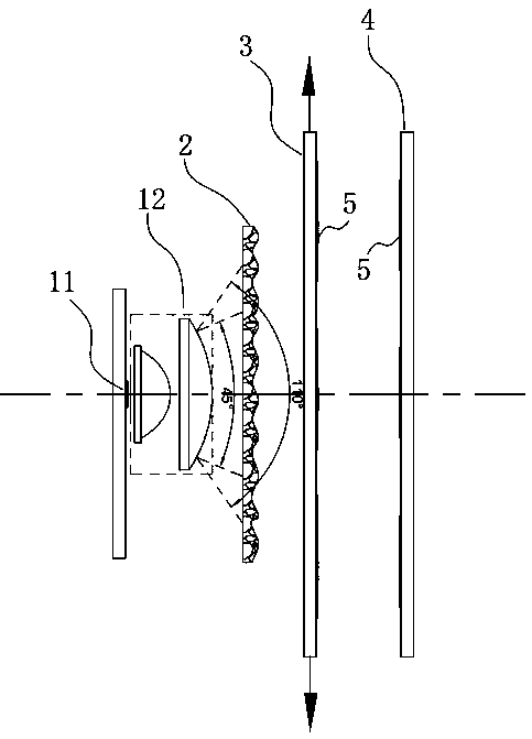
[0065] Embodiment 1. When the free-form plano-convex lens A (3) moves within its plane and the free-form plano-convex lens B (4) is fixed:

[0066] 1- The light emitted by the LED light source (11) passes through the condensing lens group (12) and converges into light at an angle of 45°-110°. The purpose of adding the condensing lens group (12) is to improve the utilization rate of the light source.

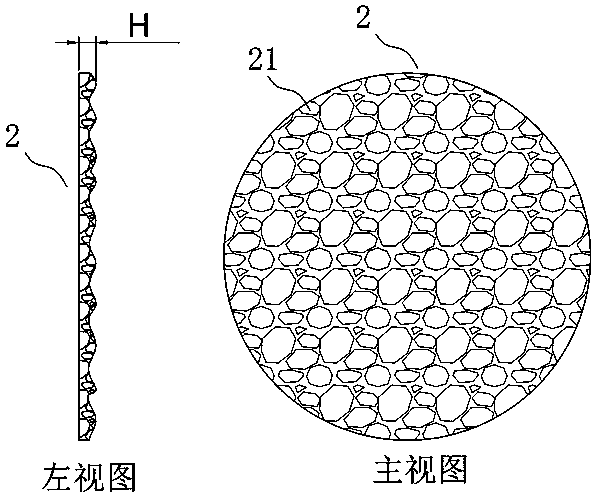
[0067] 2- The light emitted from the condensing lens group (12) enters the diffuser lens (2). Since the upper side of the diffuser lens (2) is flat, the other side includes several irregular prisms (21) with different heights, and the prisms The height H of the platform (21) is 0.2 mm ≤ H ≤ 1.4 mm, so the incident light will form a scattered nonlinear light when it exits, and the difference in light intensity passing through the prism (21) of different heights will be significantly different. as attached Figure 8 is the simulated scattered light intensity curve when the height ...

Embodiment 2

[0071] Embodiment 2. When the free-form plano-convex lens B (4) moves within its plane and the free-form plano-convex lens A (3) is fixed:

[0072] It can be understood that the optical principle of the second embodiment is the same as that of the first embodiment, the only difference is that the light passes through the free-form surface plano-convex lens A (3) to form multiple light and dark water pattern patterns and the free-form surface plano-convex The overlapping methods of the multiple light and dark water ripple patterns formed by the lens B (4) are different, that is, the 3D undulations of the water ripple patterns are different in form.

[0073] In addition, because the array arrangement of the free-form surface lens c on the free-form plano-convex lens A (3) and the free-form plano-convex lens B (4) can be completely the same or different; it is understandable that the final effect is different Also, the 3D undulations of the water pattern are different in form, bu...


PUM

PropertyMeasurementUnit
Light emitting areaaaaaaaaaaa

Abstract

According to the technical scheme, LED light sources are converged into a 45-degree to 110-degree light ray through a condensing lens, are scattered into radiating nonlinear light rays with differentlight intensity differences through an irregular prism frustum with the height of greater than or equal to 0.2 mm and less than or equal to 1.4 mm on a scattering lens and then pass through a free-form planoconvex lens A and a free-form planoconvex lens B formed by a plurality of free-form surface lenses c which are arranged in an array mode, the projection outline of the free-form surface lens cis in a water wave shape, the curvature radius R is -25mm to 25mm, and a positive and negative lens effect is achieved, so when imaging is carried out on the same imaging surface, an image with more obvious light intensity difference contrast can be formed. Moreover, the free-form planoconvex lens A or the free-form planoconvex lens B slides in the plane, and finally a 3D fluctuant light spot effect of a water wave pattern is formed.

Description

technical field [0001] The invention belongs to the field of stage and landscape lamp lighting, in particular to the field of water pattern light optical systems. Background technique [0002] The stage lighting market in modern society is more and more widely used, and there are more and more places of application. Sometimes it is necessary to let the lamps hit the buildings to produce lighting effects, which can beautify the scenery and enhance the atmosphere. The current market There are few water pattern lamps with water pattern effects in the world. This kind of water pattern lights with water pattern effects will emit the effect of flowing water, which is very beautiful and beautiful. At present, the water pattern effect of the water pattern lamp on the market has the following several ways of expression. [0003] The first is achieved by the rotation of the water pattern drum. For example, the utility model patent with the publication number CN206093600U, a new type...

Claims


Application Information

Patent Timeline
IPC IPC(8): F21K9/60F21K9/69F21V5/00F21V5/04F21V14/06F21Y115/10
CPCF21K9/60F21K9/69F21V5/002F21V5/048F21V14/06F21Y2115/10
Inventor 许法卿薛金山
Owner GUANGZHOU DASEN LIGHTING ELECTRONICS
Why Eureka
Try Eureka