Method for monitoring temperature control performance of annealing equipment

An annealing equipment and annealing temperature technology, applied in the direction of electrical components, semiconductor/solid-state device manufacturing, circuits, etc., can solve the problems of obtaining changes in working temperature, not being very effective and accurate, and poor uniformity, so as to achieve monitoring uniformity and improve The effect of validity and accuracy

Active Publication Date: 2019-08-16
SHANGHAI HUAHONG GRACE SEMICON MFG CORP
View PDF4 Cites 5 Cited by
  • Summary
  • Abstract
  • Description
  • Claims
  • Application Information

AI Technical Summary

Problems solved by technology

figure 1 It is a schematic diagram of monitoring the sheet resistance of the wafer after low-temperature annealing and its unevenness as a function of temperature. It can be seen that in the range of 420 degrees to 470 degrees, although the sheet resistance increases linearly, the uniformity is too high. In the range of 490-550 degrees, although the uniformity is very good, the resistance value of the square resistance remains basically unchanged, and it is difficult to obtain the change of the working temperature; within the range of 550-600 degrees and The situation is similar for the range of 420°-470°
[0005] Therefore, the existing monitoring methods are not very effective and accurate in monitoring the actual working temperature of the rapid annealing equipment at the low temperature annealing temperature

Method used


Image

  • Method for monitoring temperature control performance of annealing equipment
  • Method for monitoring temperature control performance of annealing equipment
  • Method for monitoring temperature control performance of annealing equipment

Examples


Embodiment Construction

[0029] The specific implementation manner of the present invention will be described in more detail below with reference to schematic diagrams. The advantages and features of the present invention will be more apparent from the following description.

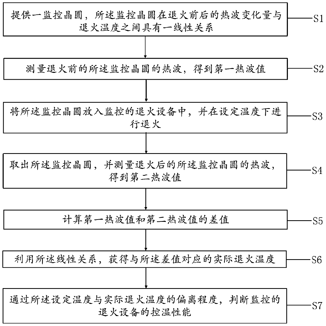
[0030] As mentioned in the background art, the existing monitoring methods cannot obtain effective and accurate results when monitoring the actual working temperature of the rapid annealing equipment. In order to improve the effectiveness and accuracy of monitoring the actual working temperature of the rapid annealing equipment, an embodiment of the present invention provides a method for monitoring the temperature control performance of the annealing equipment. figure 2 It is a schematic flowchart of a method for monitoring the temperature control performance of annealing equipment according to an embodiment of the present invention. like figure 2 As shown, the method for monitoring the temperature control performance of an...


PUM

PropertyMeasurementUnit
thicknessaaaaaaaaaa
thicknessaaaaaaaaaa

Abstract

The invention provides a method for monitoring temperature control performance of annealing equipment. The method comprises the following steps: providing a monitoring wafer, wherein the thermal wavechange amount of the monitoring wafer before and after annealing has a linear relationship with the annealing temperature; measuring the thermal wave of the monitoring wafer before and after annealingat the set temperature so as to obtain a first thermal wave value and a second thermal wave value; obtaining the actual annealing temperature corresponding to the difference between the first thermalwave value and the second thermal wave value and the linear relationship; and comparing the deviation between the set temperature and the actual annealing temperature so as to judge the temperature control performance of the monitored annealing equipment. The method for monitoring the temperature control performance of the annealing equipment can effectively and accurately monitor the temperaturecontrol performance of the annealing equipment in case of low temperature annealing.

Description

technical field [0001] The invention relates to the technical field of semiconductors, in particular to a method for monitoring the temperature control performance of annealing equipment. Background technique [0002] In the field of ultra-large-scale integrated circuits, with the reduction of chip size design rules and the scaling of devices, the limit requirements for contact resistance are getting higher and higher. The industry needed to find new alternatives, and cobalt salicide was found. During its preparation, it is usually necessary to monitor the conditions during production. For example, in the cobalt silicide-related process, including rapid thermal annealing (RTA) using rapid annealing equipment, if the annealing temperature of the rapid annealing equipment is unstable, it will have an important impact on the formed cobalt silicide and semiconductor devices. Taking flash memory as an example, if the actual temperature of the rapid annealing equipment deviates ...

Claims


Application Information

Patent Timeline
Patent Type & Authority Applications(China)
IPC IPC(8): H01L21/67H01L21/66
CPCH01L21/67098H01L21/67248H01L22/12
Inventor 李楠
Owner SHANGHAI HUAHONG GRACE SEMICON MFG CORP
Why Eureka
Try Eureka