

Movable toilet bowl
A mobile toilet technology, applied in mobile toilets, flushing equipment with water tanks, flushing toilets, etc., can solve accidents, toilets are easy to slide, etc., to avoid accidents, avoid accidents, and have strong stability Effect
- Summary
- Abstract
- Description
- Claims
- Application Information
AI Technical Summary
Problems solved by technology
Method used
Image

Examples
Embodiment 1
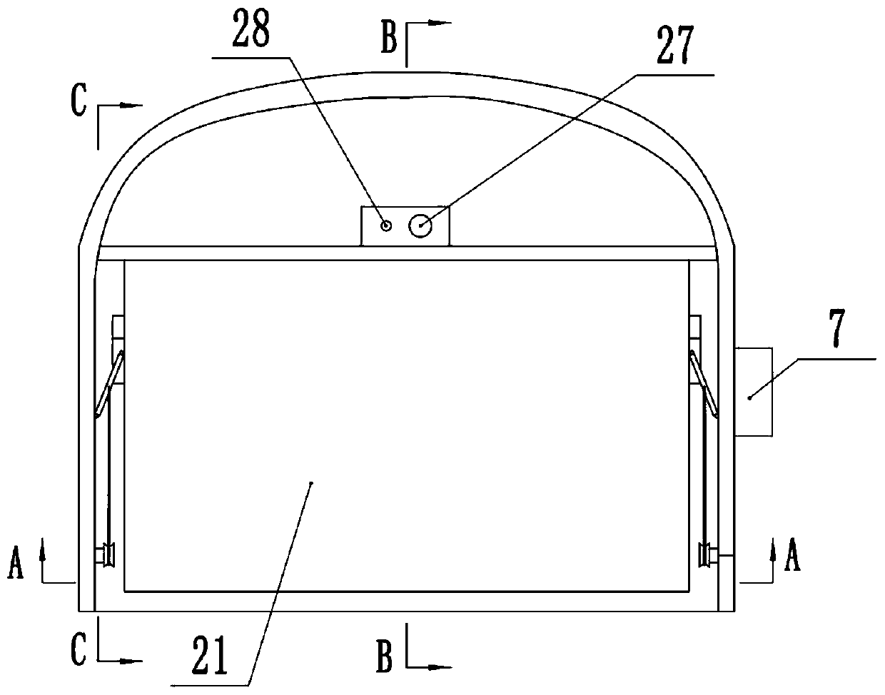
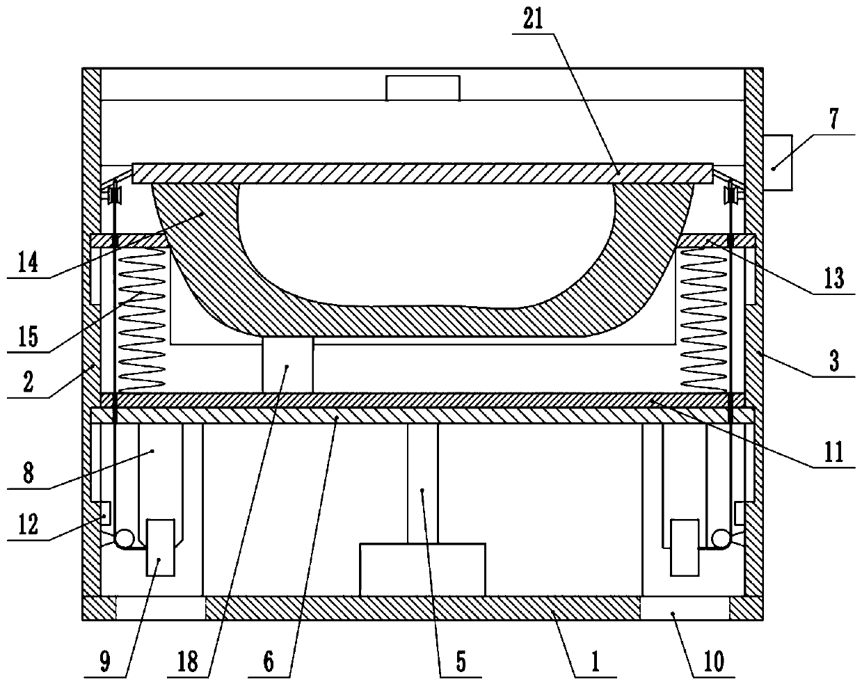
[0038] Embodiment one is basically as figure 1 , figure 2 , image 3 , Figure 4 with Figure 5 As shown, a movable toilet includes a bottom plate 1, the side of the bottom plate 1 is fixedly connected with side plates by screws, and the side plates include a left side plate 2, a right side plate 3 and a back plate 4.
[0039] Such as figure 2 As shown, the upper end of the bottom plate 1 is fixedly connected with a drive unit by screws. The drive unit includes an electric push rod 5, a drive plate 6 and a controller 7. The output shaft of the electric push rod 5 is set vertically upwards, and the top of the output shaft is connected by a screw. It is fixedly connected with the driving board 6, the left side of the driving board 6 is vertically slidingly connected with the left side board 2, and the right side and the right side board 3, and the controller 7 is fixedly connected to the outer side wall of the right side board 3 by screws On the top, the up and down push-...
Embodiment 2
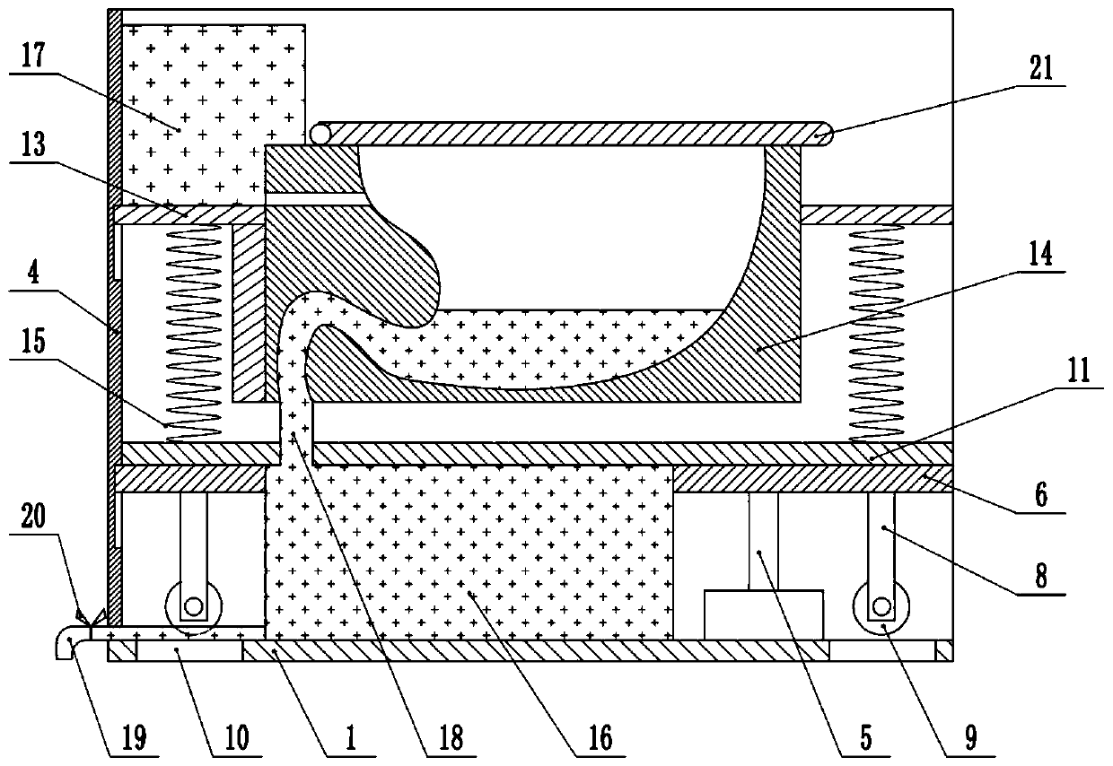
[0059] Such as Figure 7As shown, the difference between the second embodiment and the first embodiment is that the controller for controlling the electric push rod 5 is set as the first controller 29, the controller for controlling the opening and closing of the solenoid valve 20 is set as the second controller 30, and the The first controller 29 is arranged on the outside of the right side plate 3, the second controller 30 is arranged on the left side plate 2 near the sewage pipe 19, the first controller 29 and the second controller 30 are separately arranged, and the second The controller 30 is arranged at a position that cannot be easily touched, so as to prevent the second controller 30 from being opened by mistake when transferring the toilet so that the sewage in the sewage tank 16 flows out and causes ground pollution.
PUM
 Abstract
Description
Claims
Application Information