Low-resistance synchronous direct-acting type double-flapping-wing aircraft

A flapping-wing aircraft and direct-moving technology, applied to aircraft, unmanned aircraft, wings, etc., can solve the problem of inability to achieve vertical take-off and landing and hovering in the air, restricting the popularization and application of flapping-wing aircraft, and flapping-wing aircraft Low overall efficiency and other issues, to achieve the effect of simple structure, low production cost, and flapping wings synchronization

Active Publication Date: 2019-10-01
GLOBAL INST OF SOFTWARE TECH +1
View PDF8 Cites 2 Cited by
  • Summary
  • Abstract
  • Description
  • Claims
  • Application Information

AI Technical Summary

Problems solved by technology

The main reason for the overall low efficiency of flapping wing aircraft is that most of the current research simply imitates the shape and flapping motion of the wings of birds or insects, but it is difficult to realize the use of the wing's own posture and structure in the process of flapping wings of flying creatures. The change of air resistance reduces air resistance and generates unsteady aerodynamic force, and the resulting low aerodynamic efficiency seriously restricts the popularization and application of flapping-wing aircraft
At the same time, most of the current fluttering flying chess cannot realize vertical take-off and landing and hovering in the air, and their flexibility and maneuverability are not good enough.

Method used


Image

  • Low-resistance synchronous direct-acting type double-flapping-wing aircraft
  • Low-resistance synchronous direct-acting type double-flapping-wing aircraft
  • Low-resistance synchronous direct-acting type double-flapping-wing aircraft

Examples


Embodiment 1

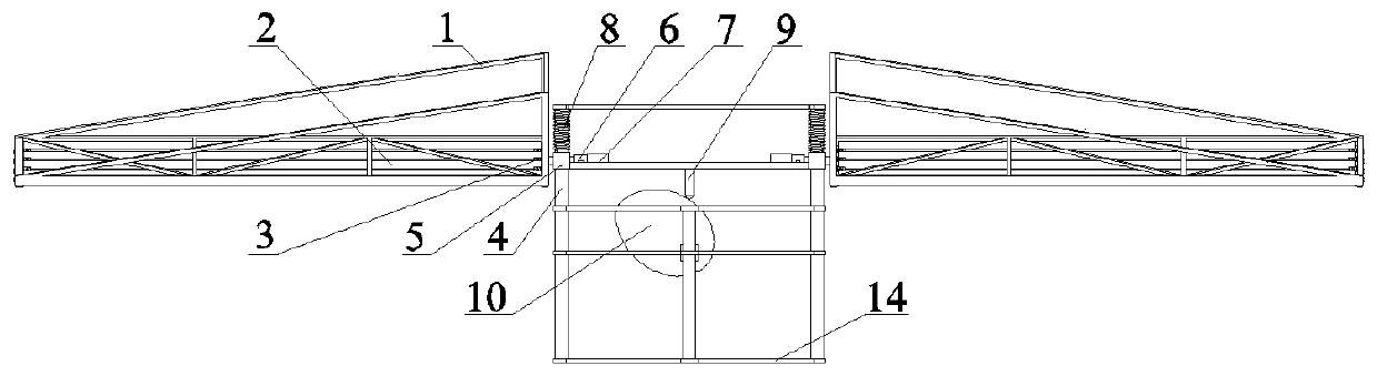
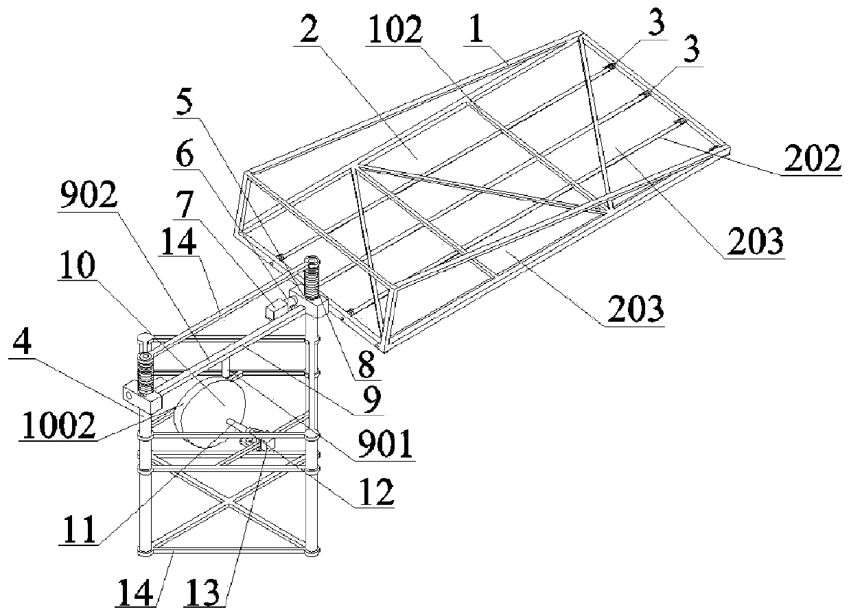
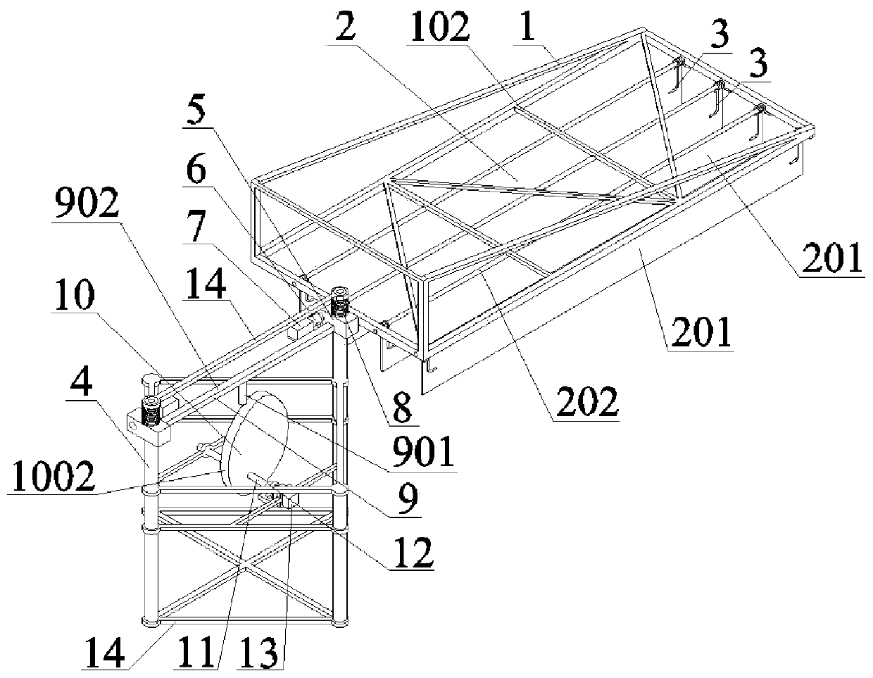
[0041] to combine figure 1 , figure 2 , image 3 , Figure 4 , Figure 5 , Figure 6 , Figure 7 , Figure 8 , Figure 9 and Figure 10 , a high-voltage wire inspection drone using a low-resistance synchronous direct-acting double flapping wing aircraft. Such as figure 1 As shown, the low-resistance synchronous direct-acting double flapping-wing aircraft includes flapping-wing frame 1, blade 2, torsion spring 3, slideway 4, connector 5, first reducer 6, stepper motor 7, spring 8, push rod 9. Cam 10, transmission shaft 11, second reducer 12, motor 13 and fuselage frame 14, blade installation hole 101, blade limit beam 102 and flapping wing shaft 103 are arranged on flapping wing frame 1, and blades are arranged on blade 2 On the windward side 201, blade shaft 202 and blade leeward side 203, there are slideway holes 501 and flapping wing shaft holes 502 on the connector 5, the axis of the slideway holes 501 is perpendicular to the axis of the flapping wing shaft holes...

Embodiment 2

[0043] This embodiment 2 provides a special drone for high-rise fire extinguishing, its structure is the same as that of embodiment 1, the difference is: the number of blades 2 in each flapping wing frame 1 is 6, the blade limit beam 102, the strengthening vertical beam 104 , Strengthening beam 105 and strengthening inclined beam 106 all adopt engineering plastics. It is a high-rise fire-fighting special UAV using a low-resistance synchronous direct-acting dual flapping wing aircraft. Including flapping wing frame 1, blade 2, torsion spring 3, slideway 4, connector 5, first reducer 6, stepping motor 7, spring 8, push rod 9, cam 10, transmission shaft 11, second reducer 12. The motor 13 and the fuselage frame 14, the flapping wing frame 1 has a blade installation hole 101, a blade limit beam 102 and a flapping wing shaft 103, and the blade 2 has a blade windward side 201, a blade shaft 202 and a blade leeward side 203, A slideway hole 501 and a flapping wing shaft hole 502 are...

Embodiment 3

[0045] This embodiment 2 provides an agricultural plant protection unmanned aerial vehicle, its structure is the same as embodiment 1, the difference is: the number of blades 2 in each flapping wing frame 1 is 8, the blade limit beam 102, the strengthening vertical beam 104, Both the reinforcing beam 105 and the reinforcing inclined beam 106 are made of engineering plastics. An agricultural plant protection UAV using a low-resistance synchronous direct-acting double flapping wing aircraft. Including flapping wing frame 1, blade 2, torsion spring 3, slideway 4, connector 5, first reducer 6, stepping motor 7, spring 8, push rod 9, cam 10, transmission shaft 11, second reducer 12. The motor 13 and the fuselage frame 14, the flapping wing frame 1 has a blade installation hole 101, a blade limit beam 102 and a flapping wing shaft 103, and the blade 2 has a blade windward side 201, a blade shaft 202 and a blade leeward side 203, A slideway hole 501 and a flapping wing shaft hole 50...


PUM


Abstract

The invention relates to the field of flapping wing type aircrafts and flying robots, in particular to a low-resistance synchronous direct-acting type double-flapping-wing aircraft. The double-flapping-wing aircraft comprises flapping wings, slideways, connecting pieces, a first speed reducer, a stepping motor, a transmission mechanism, a second speed reducer, motors and a machine body frame, wherein the two slideways in the vertical direction are symmetrically installed and fixed on two sides of the machine body frame; the two connecting pieces are respectively connected to the two slidewaysin a sliding manner; the two flapping wings are respectively connected to the two connecting pieces and can rotate relatively; the flapping wing comprises a flapping wing frame and a rotatable blade arranged in the flapping wing frame; a torsional spring is also arranged in the flapping wing frame and is used for resetting the blade; the transmission mechanism is connected to the two connecting pieces; the motors arranged on the machine body frame drive the transmission mechanism to move after being decelerated by the second speed reducer so that the two connecting pieces synchronously slide up and down; and the two stepping motors arranged on the connecting pieces drive the two flapping wings to rotate respectively after being decelerated by the first speed reducer.

Description

technical field [0001] The invention relates to the field of flapping-wing aircraft and flying robots, in particular to a low-resistance synchronous direct-acting double flapping-wing aircraft. Background technique [0002] There are three flight types of aircraft flying: fixed wing, rotary wing and flapping wing. Among them, flapping wing flight is the flying mode adopted by flying creatures in nature. It mainly uses the up and down flapping of the wings to generate lift and thrust at the same time. , hovering and propulsion functions are based on one body, and at the same time have strong maneuverability and flexibility, and are more suitable for flying around obstacles. For small-sized and low-speed aircraft flying under low Reynolds numbers, the unsteady lift generated by the flapping wing is much greater than the constant lift of the fixed wing; from the perspective of thrust, the propulsion efficiency of the flapping wing is higher than that of the propeller. [0003]...

Claims


Application Information

Patent Timeline
Patent Type & Authority Applications(China)
IPC IPC(8): B64C33/00B64C33/02B64C3/18B64C3/38B64C1/00
CPCB64C33/00B64C33/02B64C3/18B64C3/385B64C1/0009B64U2101/00
Inventor 丁荣晖邱明朱佾方世超费金陵廖振强沈凯
Owner GLOBAL INST OF SOFTWARE TECH
Why Eureka
Try Eureka