
Connecting structure for metal profile floor

A technology of metal profiles and connection structures, applied in building structures, floors, buildings, etc., can solve problems such as lack of longitudinal connection structures, and achieve the effect of improving floor installation efficiency, improving flexibility, and reducing relative movement margins

Pending Publication Date: 2019-10-11
浙江优暖家居用品有限公司
View PDF6 Cites 0 Cited by
  • Summary
  • Abstract
  • Description
  • Claims
  • Application Information

AI Technical Summary

Problems solved by technology

[0006] The technical problem to be solved by the present invention is to overcome the problem that the existing metal profile floor connection structure lacks a longitudinal connection structure, and to provide a connection structure set on the short side of the metal profile floor

Method used


Image

  • Connecting structure for metal profile floor
  • Connecting structure for metal profile floor
  • Connecting structure for metal profile floor

Examples


Embodiment 1

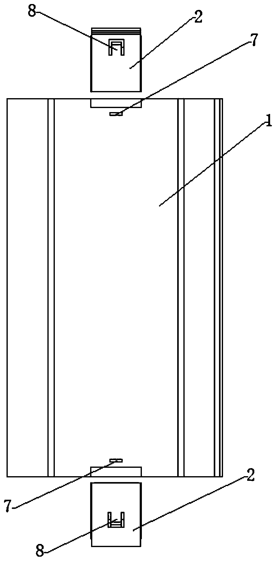
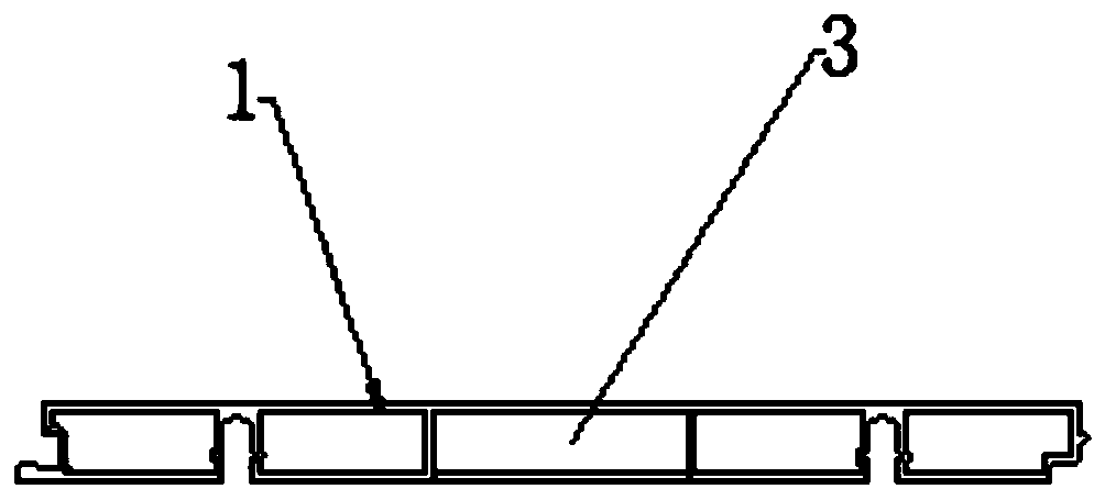
[0039] see figure 1 and figure 2 , The connection structure of the metal profile floor in the present invention includes a floor body 1 and a joint part 2 connected to the bottom body 1 . Wherein the floor body 1 is composed of a metal wire block with an inner cavity, and the short side end portions extending from the cavity to both ends of the floor body 1 constitute the installation cavity 3 .

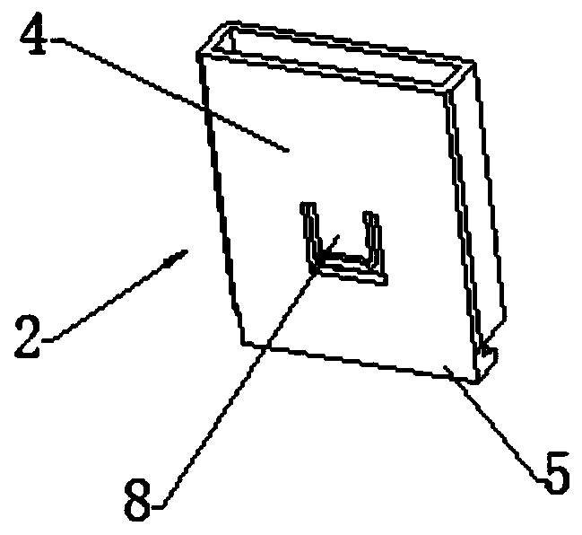
[0040] see Figure 3 to Figure 5, the joint component 2 has a fixing portion 4 and an abutting portion 5 . The abutment portion 5 is adapted to be connected with the abutment portion of the joint part on the floor adjacent to the end of the short side. The abutting portion 5 is a hook-shaped hooking structure 9, and the hook-shaped hooking surface 6 is arranged obliquely to the floor surface of the floor body 1, and the inclined angle has a shape under the pressure on the floor surface. Bring adjacent floorboards closer together. The fixing portion 4 is disposed at an end of th...


PUM


Abstract

The invention provides a connecting structure for a metal profile floor. The connecting structure comprises a floor body and joint components, and the floor body is composed of metal wire blocks withinner cavities; the cavities extend to the short edge ends of the floor body, so that a mounting cavity is formed; each joint component is provided with a fixing part and an abutting part; and the fixing parts are fittingly fixed in the mounting cavity from the short edge ends of the floor body, and the abutting parts are fittingly connected with the joint components on floors adjacent to the short edge ends. According to the connecting structure for the metal profile floor, arrangement of the connecting structure at the short edge of the metal profile floor is achieved, and the problem that connection can not be achieved effectively through the connecting structure at the longitudinal edge of the metal profile floor is solved.

Description

technical field [0001] The invention relates to the field of floor technology, in particular to a connection structure arranged on the short side of a metal profile floor. Background technique [0002] The installation of the floorboards requires fixing the floorboards to avoid uneven stress on each floorboard due to the movement of people in use and the pressing and placing of furniture. Uneven force on the floorboards will cause displacement. This displacement will make the gaps between the floorboards uneven and the floor will look messy. [0003] Usually, the floor boards are all rectangular. Since the long sides are longer, the connecting function of the long side connection structure plays a major role. Therefore, the existing floor boards generally adopt the connection structure between the horizontal adjacent blocks, while the longitudinal side The connection structure failed to effectively realize the connection. The lack of connection between the ends of longitud...

Claims


Application Information

Patent Timeline
Patent Type & Authority Applications(China)
IPC IPC(8): E04F15/02
CPCE04F15/02E04F15/02038E04F2201/03E04F2201/0523
Inventor 吕策
Owner 浙江优暖家居用品有限公司
Learn More