Self-adaptive visible light panoramic shooting system

A panorama shooting, visible light technology, applied in the parts of the TV system, the parts of the color TV, the TV and other directions, can solve the problems of blurred boundary images, underexposure, unnatural transition, etc.

A panorama shooting, visible light technology, applied in the parts of the TV system, the parts of the color TV, the TV and other directions, can solve the problems of blurred boundary images, underexposure, unnatural transition, etc.

CN110336955AInactive Publication Date: 2019-10-15易诚高科(大连)科技有限公司

Image

  • Self-adaptive visible light panoramic shooting system
  • Self-adaptive visible light panoramic shooting system
  • Self-adaptive visible light panoramic shooting system

Examples


Embodiment Construction

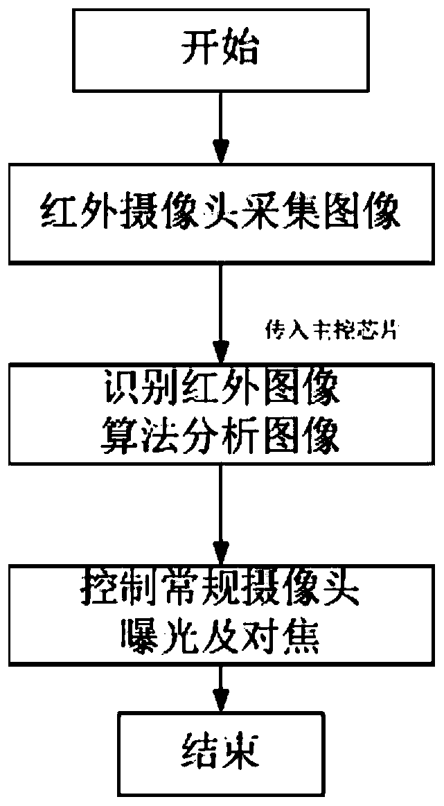
[0019] The present invention integrates and adjusts the existing panoramic camera system, uses thermal imaging technology to automatically adjust the camera, and image processing, etc., because infrared is invisible light, it can give each The optimal exposure adjustment strategy of the camera prevents the images captured by a single camera lens or multiple lenses from being seriously affected by changes in lighting conditions. The finishing process is as follows figure 1 shown.

[0020] The image acquisition method of the present invention comprises:

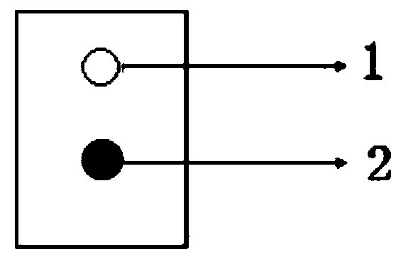
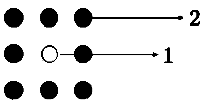
[0021] 1) One-to-one image automatic adjustment system, that is, a panoramic camera 1 and an infrared camera 2 are included in the system, and the infrared camera 2 is added directly above or directly below the panoramic camera 1. During the panoramic image shooting process, the panoramic camera lens will Rotate relatively horizontally around the Y axis of the three-dimensional space, and place the infrared camera directly ab...


PUM


Abstract

A self-adaptive visible light panoramic shooting system is characterized by comprising at least one panoramic camera and at least one infrared camera, the infrared camera collects images, and the exposure time of a panoramic lens is calculated and controlled by recognizing and processing the infrared images through an algorithm. The system can be used for unified adjustment of panoramic images imaged and exposed by a single camera and multiple cameras at the same time; panoramic images and infrared thermal images are collected in a unified mode through a thermal infrared imager and a panoramiccamera matrix, the collected images are processed through a corresponding algorithm, and therefore exposure and focusing processing of a camera is controlled, and self-adaptive visible light panoramic shooting is completed.

Description

technical field [0001] The invention relates to the field of imaging technology. Background technique [0002] The current panoramic image acquisition methods include: [0003] 1) Static panoramic shooting with a single camera, that is, image shooting with a wide-angle camera; [0004] 2) Single-camera dynamic shooting, that is, using the camera to rotate and shoot, and then stitching pictures; [0005] 3) Double-lens panoramic shooting, that is, using two wide-angle cameras to take panoramic pictures, and then image stitching; [0006] The above schemes are simple and fast, and have their own advantages and disadvantages on the whole. The light sensor is used for calibration and adjustment. The wide-angle camera under a single camera still has a lack of viewing angle. Adjust the best image effect, single-camera dynamic shooting, the shooting process is due to the different external lighting conditions under different viewing angles of the external environment, during the...

Claims


Application Information

Patent Timeline
15 Oct 2019
Publication
CN110336955A
IPC
H04N5/235; H04N5/232; H04N5/247; H04N5/33; H04N23/90
CPC
H04N5/33; H04N23/698; H04N23/73; H04N23/90
Inventors
贾立昕; 柏松