Cable bridge module for flexibly linking connection terminals

A technology for connecting terminals and cable bridges, which is applied in the field of cable bridge modules, and can solve problems such as complex geometric design of jumpers

Active Publication Date: 2019-10-22
PHOENIX CONTACT GMBH & CO KG
View PDF6 Cites 0 Cited by
  • Summary
  • Abstract
  • Description
  • Claims
  • Application Information

AI Technical Summary

Problems solved by technology

[0005] If the connection terminals to be bridged to each other are arranged geometrically complex, for example locked on different support rails, then the geometric design of the jumper for bridging the connection terminals is also complicated by this

Method used


Image

  • Cable bridge module for flexibly linking connection terminals
  • Cable bridge module for flexibly linking connection terminals
  • Cable bridge module for flexibly linking connection terminals

Examples


Embodiment Construction

[0043] In the following description, the same reference signs indicate the same parts or the same features, so that the description of one part with reference to one drawing is also applicable to other drawings to avoid repetitive descriptions. In addition, each feature described on the basis of one embodiment can also be used separately in other embodiments.

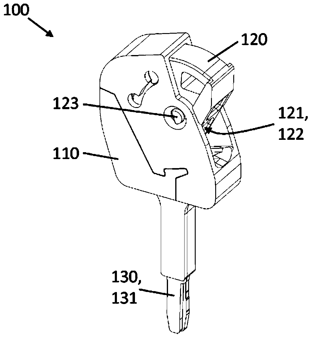
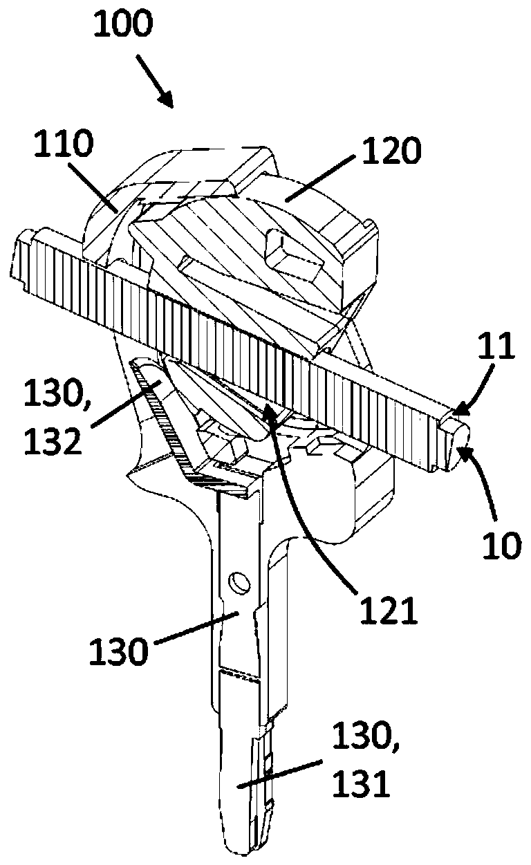
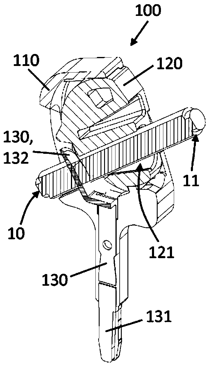
[0044] Figure 1A A perspective view of the cable bridge module 100 according to the first embodiment of the present invention is shown. The cable bridge module 100 is configured to electrically bridge two electrical connection terminals 20 (see Figure 2A with 2B ), wherein the connecting terminals 20 respectively have bridge wells 23 through which the conductive rails of the corresponding connecting terminals 20 can be contacted respectively.

[0045] The cable bridge module 100 has an electrically insulating housing 110 in which electrical contacts 130 are arranged. The electrical contact 130 has a first contact area 131 ...


PUM


Abstract

The invention relates to a cable bridge module (100, 200) for electrically bridging two electrical connection terminals (20), each of which has a bus bar and a bridge shaft (23), by means of which thebus bar can be electrically contacted, the cable bridge module comprising: an electrically insulating housing (110, 210); a conductor receptacle (121, 211) for receiving an electrical conductor (10);an electrical contact (130, 230) having a first contact region (131, 231) protruding out of the housing (110, 210) for electrically contacting a bus bar of a connection terminal (20) and having a second contact region (132, 232) arranged in the housing (110, 210) for electrically contacting the electrical conductor (10); and an actuating element (120, 220), which can be moved relative to the housing (110, 210) between a receiving position, in which the electrical conductor (10) can be inserted into the conductor receptacle (121, 211), and a contact position, in which the electrical conductor(10) is galvanically connected to the second contact region (132, 232).

Description

Technical field [0001] The invention relates to a cable bridge module for electrically bridging two electrical connection terminals. Background technique [0002] An electrical connection terminal is known from the prior art, and it is generally configured as a connection terminal used in wiring of electrical equipment and instruments. The connection terminals are usually locked on a support rail, and the support rail itself is usually arranged in multiples in the switch cabinet. As conductor connection elements, screw terminals or traction spring terminals are usually used in connection terminals. But in addition to this, it is also possible to use cut connection terminals or spiral torsion spring terminals. [0003] The connecting terminal has at least two conductor connecting elements, which are electrically connected to each other via a conductive connecting rail and a conductive rail. In addition to this basic type, which is also commonly referred to as a through terminal, ...

Claims


Application Information

Patent Timeline
IPC IPC(8): H01R4/2433H01R9/24H01R31/08H01R9/26
CPCH01R4/2433H01R9/2458H01R9/2675
Inventor 马赛尔·威廉斯于尔根·布兰德
Owner PHOENIX CONTACT GMBH & CO KG
Why Eureka
Try Eureka