
Steering wheel structure

A steering wheel and guide technology, which is used in steering mechanisms, steering rods, steering controls mounted on vehicles, etc., and can solve problems such as the number of complex parts

Active Publication Date: 2019-11-08
ASHIMORI INDS +1
View PDF7 Cites 2 Cited by
  • Summary
  • Abstract
  • Description
  • Claims
  • Application Information

AI Technical Summary

Problems solved by technology

[0004] In the structures described in each patent document, the mechanism for installing the airbag module on the steering wheel by both the dynamic damping function and the buckle method is quite complicated and requires a large number of parts. Therefore, it is hoped that at this point take countermeasures

Method used


Image

  • Steering wheel structure
  • Steering wheel structure
  • Steering wheel structure

Examples


Embodiment Construction

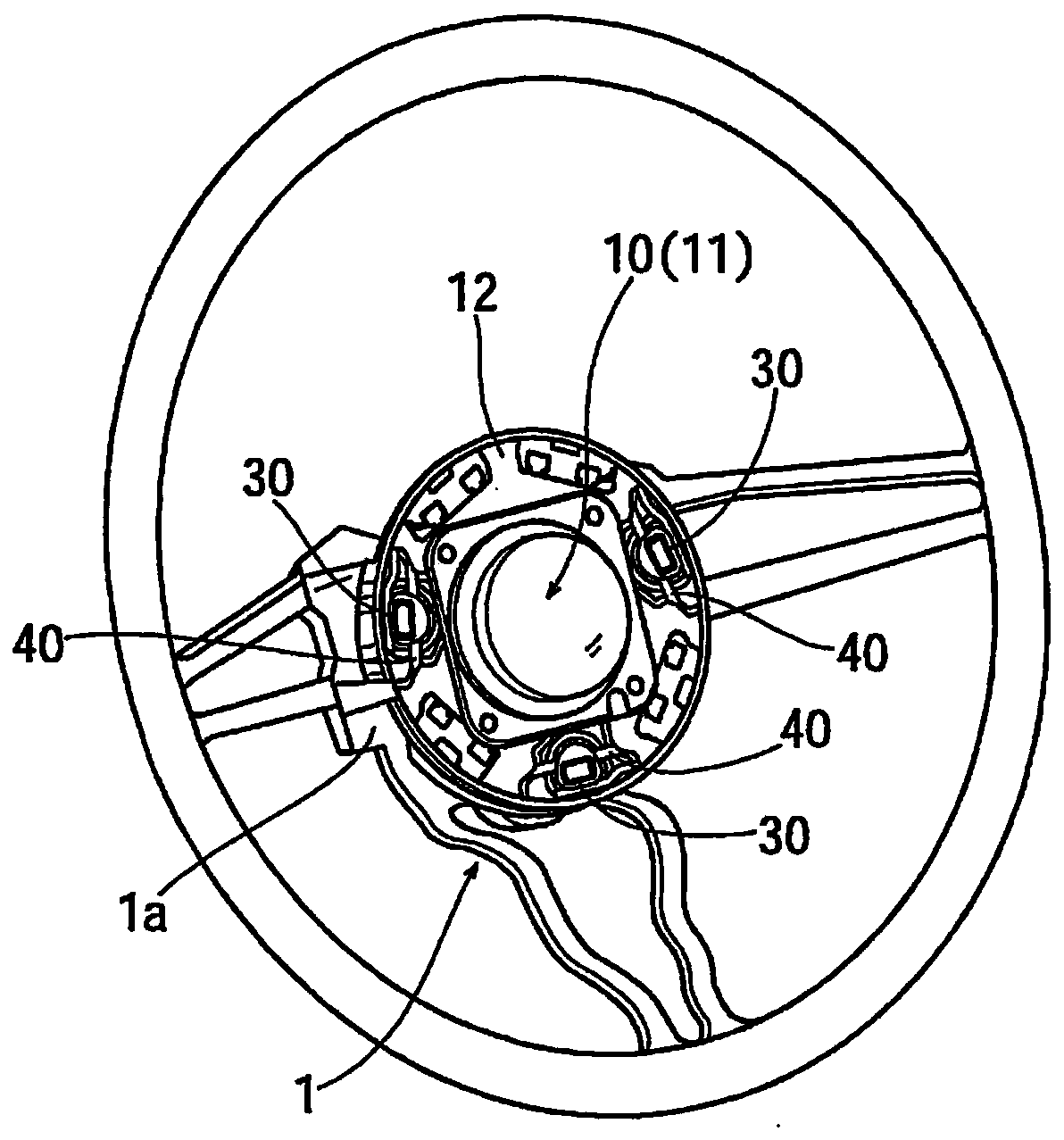
[0027] figure 1 Among them, 1 is the core bone of the steering wheel. The metal core 1 has a hub portion 1a. As will be described later, the airbag module 10 is attached to the hub portion 1a.

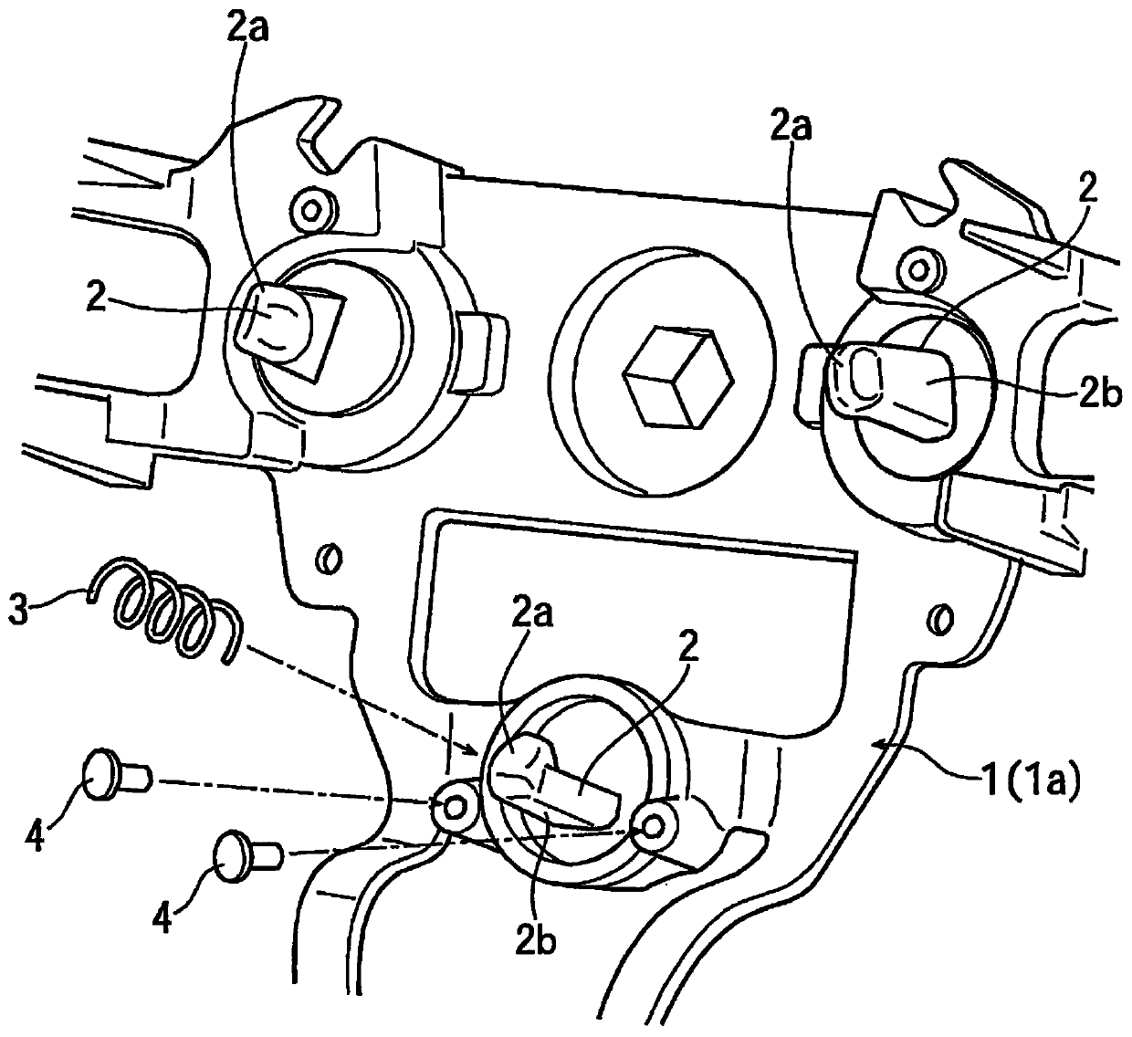
[0028] Such as image 3 As shown, in the hub portion 1a of the steering wheel (core bar 1), a plurality of (three in this embodiment) hook portions 2 protrude rearward (rearward when the steering wheel is assembled in the vehicle). form. Each hook portion 2 is integrally formed with the metal core 1 by, for example, casting. Each hook portion 2 has a tapered enlarged distal end portion 2a. The enlarged distal end portion 2a functions as a locking claw. Furthermore, a predetermined position in the circumferential direction in the side surface of each hook portion 2 is formed as a flat surface 2b.

[0029] A return spring 3 constituted by a coil spring is attached to the outer periphery of the hook portion 2 . The detachment of the return spring 3 from the hook 2 is restricted ba...


PUM


Abstract

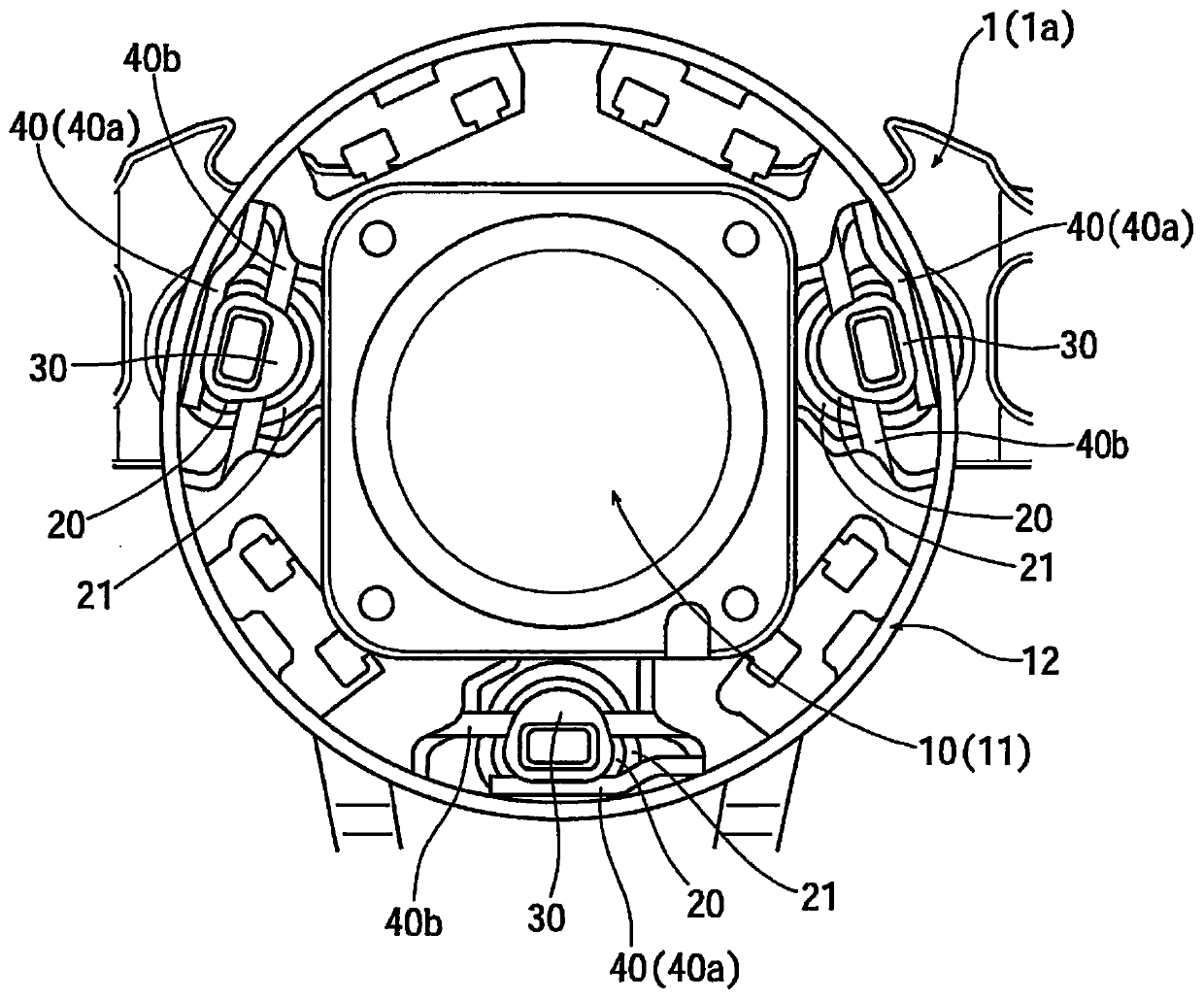
This steering wheel structure comprises: a cylindrical guide member (30) held in a mounting hole (12a) formed in the mounting plate section (12) of an air bag module (10); a hook section (2) formed ona steering wheel (1) and inserted in the guide member (30); damper rubber (20) disposed between the guide member (30) and an edge of the mounting hole (12a) in the mounting plate section (12); and alock spring (40) held by the guide member (30). The lock spring (40) is engaged with the hook section (2) inserted in the guide member (30), thereby preventing the hook section (2) from becoming dislodged from the guide member (30).

Description

technical field [0001] The present invention relates to steering wheel structures. Background technique [0002] The airbag for the driver's seat is usually modularized and attached to the hub portion of the steering wheel. Among methods of mounting a modular airbag for a driver's seat (hereinafter referred to as an airbag module) to a steering wheel, a relatively simple method called a snap-in method is known. In addition, in order to realize the dynamic damping function to reduce the vibration of the steering wheel during driving, the airbag module, which is a mass body, is elastically attached to the steering wheel. [0003] The following Patent Document 1 and Patent Document 2 disclose structures in which the airbag module can be attached to the steering wheel by snapping while realizing the dynamic damping function. [0004] In the structures described in each patent document, the mechanism for installing the airbag module on the steering wheel by both the dynamic dam...

Claims


Application Information

Patent Timeline
IPC IPC(8): B60R21/203B62D1/04
CPCB62D7/222B60R21/2037B60R21/203B62D1/04B60Y2410/113
Inventor 南雄太比护秀矩行松健一归山秀治
Owner ASHIMORI INDS
Learn More