Active clamp fly-back converter

A flyback converter and clamping technology, applied in instruments, converting DC power input to DC power output, adjusting electrical variables, etc., can solve the problem of obvious leakage inductance oscillation in the demagnetization stage of the transformer, and achieve improved leakage inductance oscillation, The effect of reducing switching loss and reducing magnetizing current

Active Publication Date: 2019-11-15
MORNSUN GUANGZHOU SCI & TECH
View PDF2 Cites 7 Cited by
  • Summary
  • Abstract
  • Description
  • Claims
  • Application Information

AI Technical Summary

Problems solved by technology

The solution proposed by this patent can realize the ZVS of the main power switch S1 at light load, and solve the oscillation problem in the intermittent rest stage at the same time, bu

Method used


Image

  • Active clamp fly-back converter
  • Active clamp fly-back converter
  • Active clamp fly-back converter

Examples


Embodiment Construction

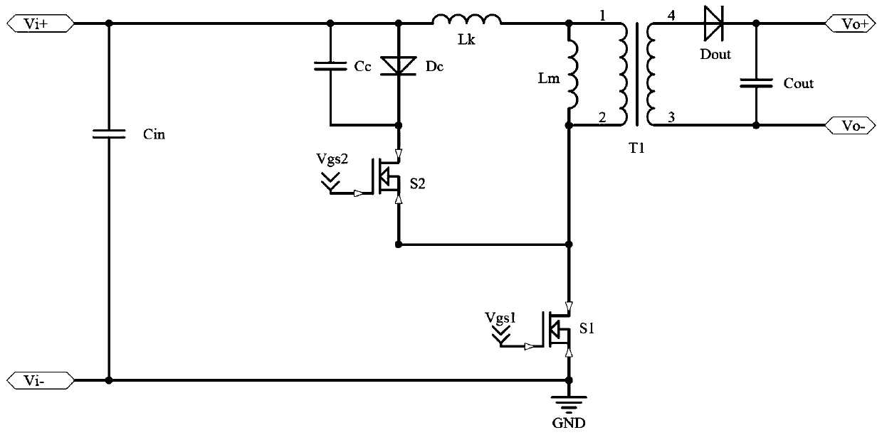
[0041] by Figure 4 Based on the principle diagram of the active clamp flyback converter of the present invention shown, the following detailed description will be made.

[0042] Figure 4 and figure 2 The difference is that the active clamp circuit includes the main clamp circuit and the auxiliary clamp circuit; the main clamp circuit includes the main clamp switch S2 and the main clamp capacitor Cr, the main clamp switch S2 and the main clamp capacitor Cr is connected in parallel at both ends of the primary winding of the main power transformer T1; the auxiliary clamp circuit includes the auxiliary clamp switch S3 and the auxiliary clamp capacitor Cc, and the auxiliary clamp switch S3 and the auxiliary clamp capacitor Cc are connected in parallel in the main The two ends of the primary winding of the power transformer T1, the auxiliary clamp circuit also includes a diode Dc connected in parallel with the auxiliary clamp capacitor Cc, the anode of the diode Dc is electricall...


PUM


Abstract

The invention discloses an active clamp fly-back converter, which comprises an active clamp circuit, an isolation feedback module and a controller. The converter is characterized in that the active clamp circuit consists of a main clamp circuit and an auxiliary clamp circuit; the isolation feedback module is used to detect a load current, generate a current detection signal related to the load current and transmit the current detection signal to the controller. The controller controls the working mode of the active clamp fly-back converter according to the current detection signal, wherein theconverter enters a double-clamp working mode when the current detection signal is higher than a predetermined value, and the converter enters a single-clamp working mode when the current detection signal reaches or is lower than the predetermined value. Compared with the prior art, by using mode switching, the efficiency of the circuit under heavy load is ensured, the efficiency when the load becomes light is improved, and the problem of oscillation in the circuit due to leakage inductance is eliminated; and by using a scheme of clamp switch tube driving transition, the system stability is improved, and the service life of the device is prolonged.

Description

technical field [0001] The invention relates to the field of switching converters, in particular to an active clamp flyback converter. Background technique [0002] The traditional active clamping circuit consists of a clamping switch tube and a clamping capacitor in series, which are connected in parallel at both ends of the main power switch tube or the primary winding of the main power transformer. The flyback converter with an active clamping circuit is generally called Active clamp flyback converter, the active clamp flyback converter can not only absorb the leakage inductance energy, but also feed back the leakage inductance energy to the output terminal and realize the soft switching of the switching tube, which is improved compared with the ordinary flyback converter The efficiency is improved, so the traditional active clamp flyback converter is favored by designers. [0003] The traditional active clamp flyback converter can realize the competent ZVS (Zero Voltage...

Claims


Application Information

Patent Timeline
IPC IPC(8): H02M3/335
CPCH02M3/33569
Inventor 尹向阳马守栋李永昌钟天明
Owner MORNSUN GUANGZHOU SCI & TECH
Why Eureka
Try Eureka