Steel wire stamping machine and method for processing aluminum block by steel wire stamping machine

A technology of punching machine and steel wire, which is applied to steel wire punching machine and processing field for installing steel wire in aluminum block, can solve the problems of hidden danger, low assembly efficiency, labor consumption of operators, etc., and achieve the effect of reducing hidden danger and improving processing efficiency.

Active Publication Date: 2020-12-22
佛山市南海三力阳蓬有限公司
View PDF5 Cites 0 Cited by
  • Summary
  • Abstract
  • Description
  • Claims
  • Application Information

AI Technical Summary

Problems solved by technology

[0003] The existing assembly methods of aluminum blocks and steel wires basically rely on manually bending the steel wires first, then inserting the bent steel wires into the holes of the aluminum blocks, and placing the aluminum blocks with the steel wires inserted on the press , the pressure column on the press press is pressed on the aluminum block, so that the aluminum block is deformed and squeezed around the steel wire, so that the steel wire and the aluminum block are connected together. The current assembly method has low assembly efficiency, and the steel wire is bent and interspersed with the aluminum block. It takes a lot of energy for the operator to work in the block, and it is difficult to work continuously for a long time. In addition, there is a great potential safety hazard in bending the steel wire into the aluminum block.

Method used


Image

  • Steel wire stamping machine and method for processing aluminum block by steel wire stamping machine
  • Steel wire stamping machine and method for processing aluminum block by steel wire stamping machine
  • Steel wire stamping machine and method for processing aluminum block by steel wire stamping machine

Examples


Embodiment Construction

[0034] The present invention will be described in further detail below in conjunction with the accompanying drawings.

[0035] Figure 1 to Figure 5 Schematically shows the structure of a wire punching machine according to an embodiment of the present invention.

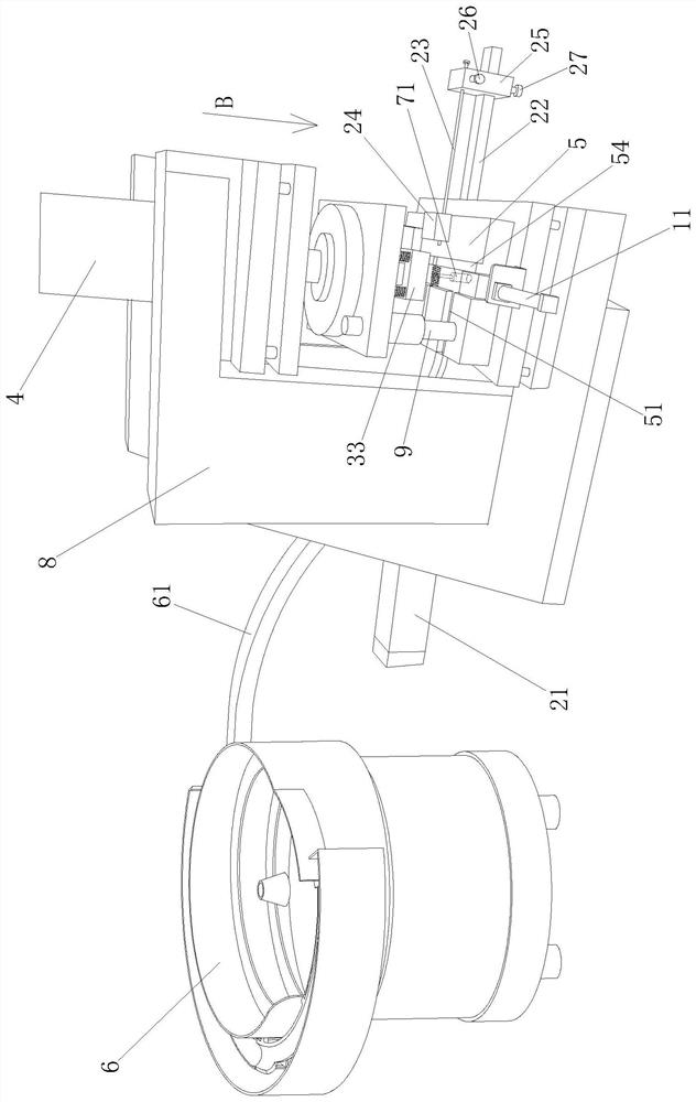
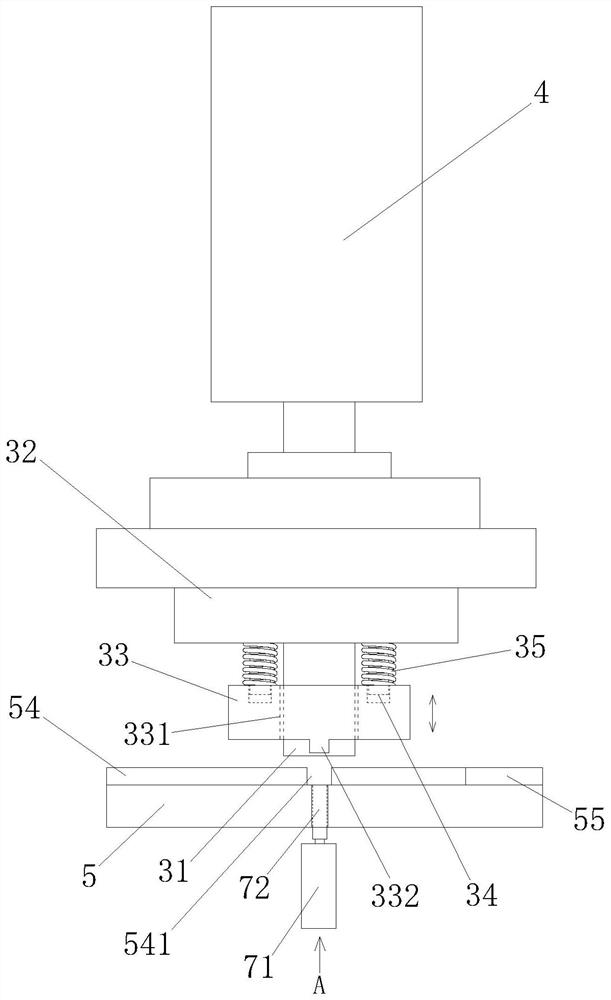
[0036] Such as Figure 1 to Figure 4 As shown, the steel wire stamping machine includes clamping parts, punching parts, pressing parts and driving parts 4 . In addition, the steel wire punching machine may also include a base 5 , a vibrating plate 6 , a mandrel component, a frame 8 and a guide column 9 .

[0037] Such as Figure 4 As shown, the base 5 is formed with a conveying channel A51, a conveying channel B52, and an accommodating channel 53. The conveying channel A51 communicates with the conveying channel B52 and is arranged vertically. The width of the channel A51 is slightly larger than the width of the aluminum block, and the longitudinal aluminum block is transported horizontally in the conveying channel...


PUM


Abstract

The invention discloses a steel wire punching machine and a method for machining an aluminum block through the steel wire punching machine. The steel wire punching machine and the method for machiningthe aluminum block through the steel wire punching machine comprise a clamping part, a top punching part, a pressing part and a driving part; the clamping part can clamp and position the aluminum block under the pressing part, and the steel wire is placed between the aluminum block and the top punching part; the steel wire can be bent and inserted into the aluminum block through the top punchingpart; the pressing part moves downwards to be pressed on the aluminum block, and the aluminum block is deformed and extruded on the periphery of the steel wire, so that the steel wire is connected with the aluminum block; and the bending part of the steel wire extends out of the aluminum block to form a hanging ring pattern so as to be used for installing a spring in a folding crank arm. The assembling operation of the aluminum block and the steel wire is simple, and an operator only needs to place the steel wire between the aluminum block and the top punching part without manual bending of the steel wire; and the aluminum block inserted with the steel wire is not required to be transferred to a press bed manually, thus greatly improving the assembling efficiency and saving time and labor.

Description

technical field [0001] The invention relates to a steel wire punching machine and a method for processing an aluminum block by the steel wire punching machine, in particular to a steel wire punching machine and a processing method for installing steel wires corresponding to the aluminum block used in the folding crank arm of an awning. Background technique [0002] In the folding crank arm of the awning, one end of the spring is hooked on the end joint of the folding crank arm, and the other end of the spring is hung on the middle joint of the folding crank arm through a steel wire. The two ends of the steel wire need to be installed in an aluminum block respectively. Formed in the form of a hanging loop, one end is connected to the spring, and the aluminum block at the other end rests on the groove on the middle joint, so that the spring in the folding crank arm is in tension. [0003] The existing assembly methods of aluminum blocks and steel wires basically rely on manual...

Claims


Application Information

Patent Timeline
Patent Type & Authority Patents(China)
IPC IPC(8): B21F15/00
CPCB21F15/00
Inventor 蔡彦飞李浩良周双
Owner 佛山市南海三力阳蓬有限公司
Why Eureka
Try Eureka