
Iron core group of magnetic offset type linear motor

A linear motor, core group technology, applied in the direction of magnetic circuit shape/style/structure, etc., can solve the problems of inability to improve manufacturing efficiency, increase manufacturing burden, increase difficulty in quality, etc., to simplify the assembly process, improve efficiency, and facilitate assembly. and processing effect

Inactive Publication Date: 2016-05-11
HIWIN MIKROSYST
View PDF3 Cites 0 Cited by
  • Summary
  • Abstract
  • Description
  • Claims
  • Application Information

AI Technical Summary

Problems solved by technology

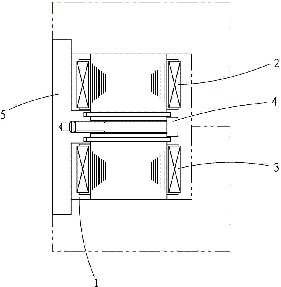
[0004] However, these technical contents for constituting the double-sided coil windings must sequentially assemble each plate-shaped tooth 1 on the base plate 5, and there are too many joint parts, so that the structural strength is not ideal, and it must be assembled one by one. Each plate-shaped tooth 1 is fixed on the base plate 5 separately. In addition to the cumbersome assembly process, special tools are required for assembly and processing, which only increases the burden on manufacturing, fails to improve manufacturing efficiency, and increases quality control. relative difficulty

Method used


Image

  • Iron core group of magnetic offset type linear motor
  • Iron core group of magnetic offset type linear motor
  • Iron core group of magnetic offset type linear motor

Examples


Embodiment Construction

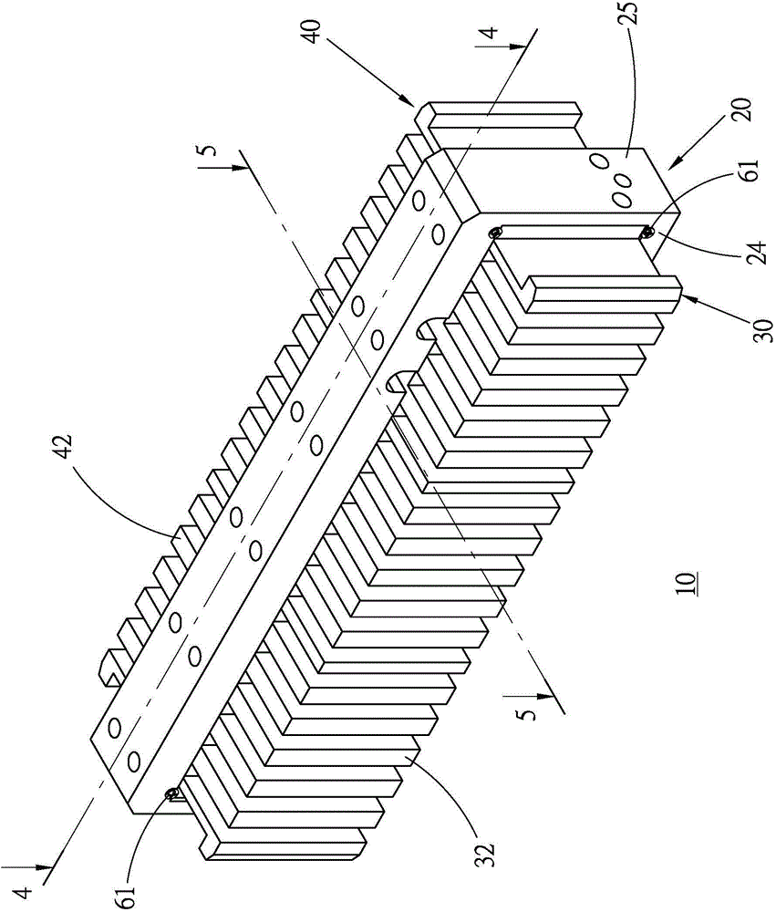
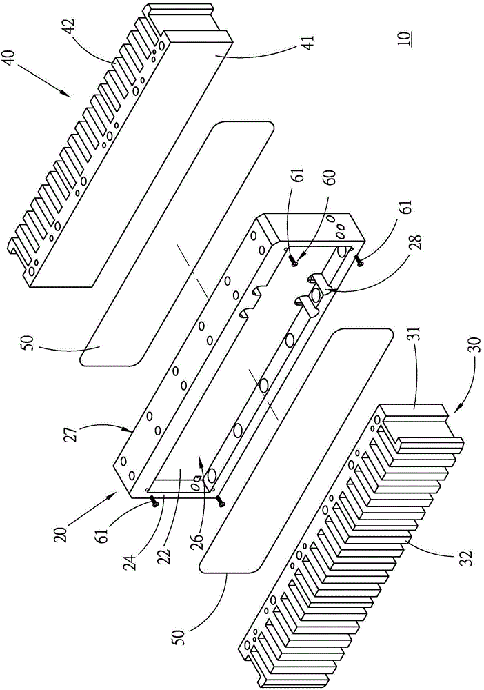
[0026] First, see Figure 2 to Figure 5 As shown, the core structure 10 of the magnetic phase braking linear motor provided in a preferred embodiment of the present invention mainly includes a base 20, a first core piece 30, a second core piece 40, and two heat conducting parts 50 and two fixing parts 60.

[0027] The base 20 is made of a non-magnetic material such as aluminum, and has a plate-shaped seat body 21 of appropriate thickness. The flat first end surface 22 and the second end surface 23 are respectively located on the opposite side plates of the seat body 21. On the side, a ring-shaped first positioning wall 24 protrudes from the first end surface 22 and corresponds to the position of the peripheral side plate end of the seat body 21, and a ring-shaped second positioning wall 25 is similar to the first end surface 22. The setting of a positioning wall 24 generally protrudes on the second end surface 23, so that the first positioning wall and 24 and the first end su...


PUM


Abstract

The invention provides an iron core group of a magnetic offset type linear motor. The iron core group includes a base which is provided with a first end surface and a second end surface which backs onto the first end surface, a first iron core component which is fixedly arranged on the first end surface, and a second iron core component which is fixedly arranged on the second end surface; the base is provided with a base body; the first end surface is formed at one side base surface; a first ring-shaped positioning wall, protruding out from the first end surface, is arranged on the first end surface, and surrounds the peripheral side of the first iron core component; the first iron core component is provided with a first bottom portion which is attached to the first end surface at one side end surface, so that the peripheral side of the first iron core component can abut against the first positioning wall; and the first iron core component is also provided with a plurality of teeth which are distributed in a gridded manner and are arranged on the other side end surface of the first bottom portion and protrude out from the other side end surface of the first bottom portion. With the iron core group of the invention adopted, the efficiency of assembly and processing can be improved. The overall mechanical strength of the iron core group can be increased.

Description

technical field [0001] The invention relates to electric motors, in particular to an iron core group of a magnetic phase braking linear motor. Background technique [0002] According to the linear motor, the stator is extended linearly, and the mover is reciprocated along the linear direction of the stator. The principle is the same as that of the traditional rotary motor. Therefore, in the description, they are all expanded. Rotary motors are compared to linear motors, but the two are still different in specific technical content. For example, linear motors are divided into iron-core linear motors and iron-less linear motors because of whether they have iron cores in their composition. , there are different kinetic energy output modes between the two, which can meet different application requirements. [0003] As far as the iron-core linear motor is concerned, the iron core it has can be further divided into different tooth configurations for single-sided winding and doubl...

Claims


Application Information

Patent Timeline
Patent Type & Authority Applications(China)
IPC IPC(8): H02K1/06
Inventor 曾胜煜邓朝钦纪政德
Owner HIWIN MIKROSYST
Learn More