Plate-exchanging device of printing units for printing presses

A technology for printing devices and printing machines, applied in printing machines, general parts of printing machinery, printing, etc., can solve problems such as printing surface protection that cannot be printed

Inactive Publication Date: 2003-04-23
HEIDELBERG HARRIS +1
View PDF7 Cites 0 Cited by
  • Summary
  • Abstract
  • Description
  • Claims
  • Application Information

AI Technical Summary

Problems solved by technology

[0007] All the aforementioned solutions have the disadvantage of requiring a large number of moving parts, which limits access to the printing unit, even when these parts are not in use
Also, some of the solutions mentioned do not always guarantee a good protection of the printing surface of the plate

Method used


Image

  • Plate-exchanging device of printing units for printing presses
  • Plate-exchanging device of printing units for printing presses
  • Plate-exchanging device of printing units for printing presses

Examples


Embodiment Construction

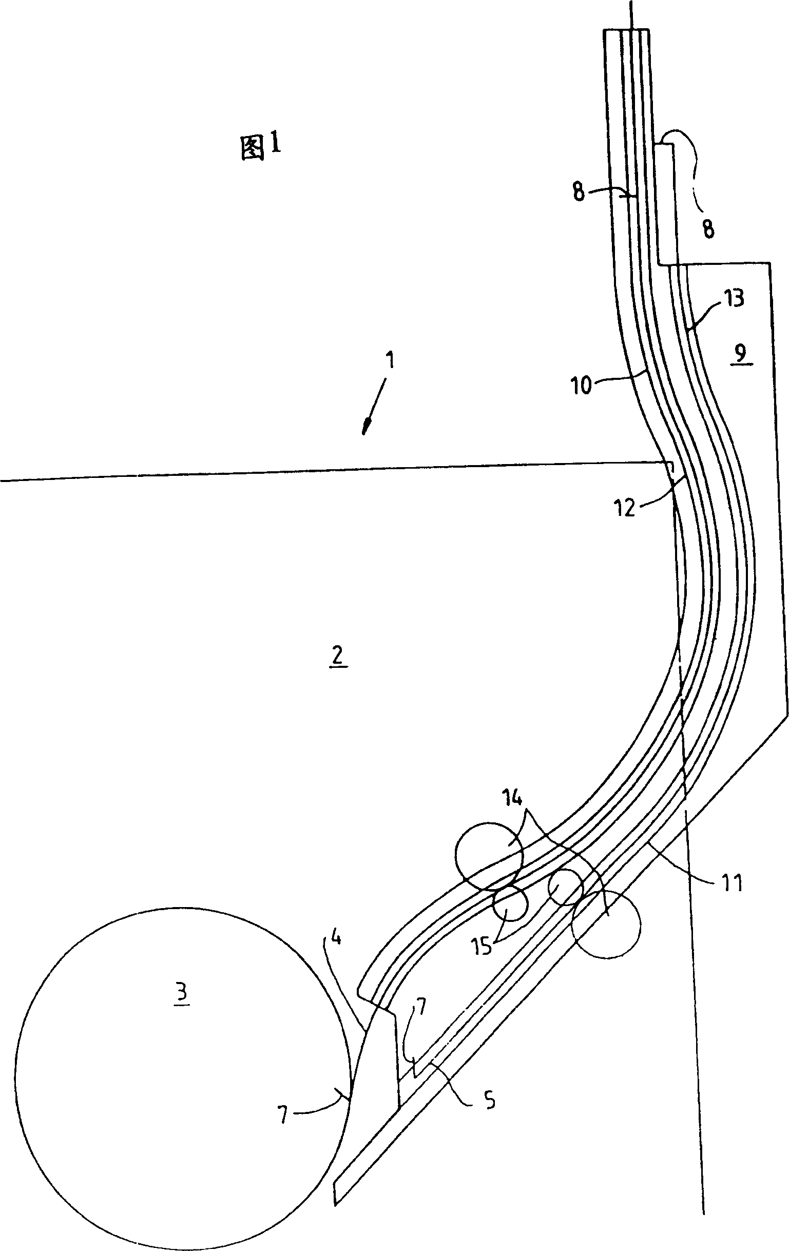
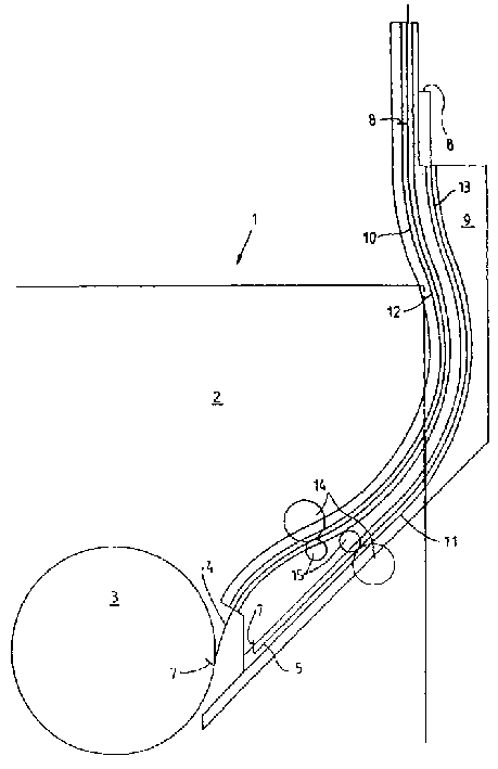
[0016] FIG. 1 shows the solution proposed by the present invention for the upper plate cylinder 3 of the printing device 1. For a device that performs printing on both sides of the connected web, the device of the present invention can also be installed for the lower plate cylinder without difficulty.

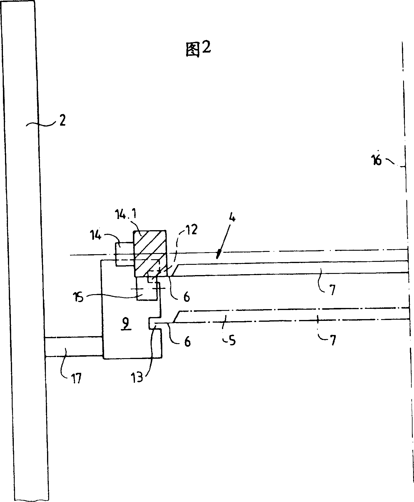
[0017] The master body 9 is fixed to each of the two supporting frames 2 of the printing device 1. At least one first printing plate 4 is placed on each of these profiling bodies 9, which is a new printing plate, which will be installed on the corresponding printing plate cylinder 3 of the printing device 1, and at least one second printing plate 5 is also placed. It was unloaded from the plate cylinder 3 in advance. Each printing plate 4 and 5 has a front edge 7 and a rear edge 8, which are introduced on the periphery of the printing plate cylinder 3 and fix them to a gripping device on the periphery. The lateral edges 6 of the printing plate (see Fig. 2) are guided in the masters...


PUM


Abstract

Device for exchanging printing forms on a form cylinder in a printing unit of a rotary printing press, a holding device being provided in the printing unit for both holding therein at least one printing form which is to be installed, as well as at least one printing form which is being removed, includes profile members for guiding the printing forms substantially by lateral regions thereof.

Description

Technical field [0001] The invention relates to a printing plate replacement device on a printing plate cylinder in a printing device of a rotary printing machine. The printing plate replacement device can place at least one printing plate to be installed on the one hand, and at least one printing plate that has just been removed on the other hand. . Background technique [0002] Existing documents, such as EP0503750, have already described the plate changing device. [0003] According to this document, EP0530750, the printing plate support provided on the printing device table supports the rear edge of the printing plate to be installed during the installation of the printing plate to the printing plate cylinder. [0004] The document EP0530565 describes a device that plans to automatically change printing plates. Several printing plates for replacement are placed in the device in opposite directions, and a filling box that holds several printing plates can be placed in the devi...

Claims


Application Information

Patent Timeline
IPC IPC(8): B41F27/12
CPCB41F27/1206
Inventor 雅克·梅特罗普
Owner HEIDELBERG HARRIS
Why Eureka
Try Eureka