
Bending mechanism, method for making bending plate through bending mechanism and bending plate

A technology of bending mechanism and bending plate, applied in the field of bending plate, which can solve the problems affecting the appearance of products

Pending Publication Date: 2020-01-03
ZHUHAI GREE PRECISION MOLD CO LTD +1
View PDF0 Cites 0 Cited by
  • Summary
  • Abstract
  • Description
  • Claims
  • Application Information

AI Technical Summary

Problems solved by technology

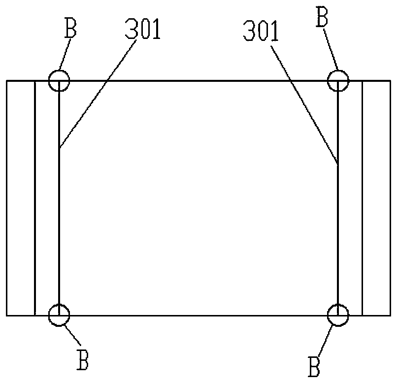
[0002] At present, sheet metal parts often have a small hem on the bend, that is, a primary hem on the secondary hem. The traditional method is to fold a whole circle of the small hem first, that is, to fold a whole circle of the primary hem first. , and then fold the large bend of the product, that is, fold the secondary edge again, and the product will often bulge outward at the intersection of the bend, such as figure 1 As shown, the position where the secondary bending position 301 meets the primary hem, that is, the position B in the figure bulges outward, and this defect seriously affects the appearance of the product

Method used


Image

  • Bending mechanism, method for making bending plate through bending mechanism and bending plate
  • Bending mechanism, method for making bending plate through bending mechanism and bending plate
  • Bending mechanism, method for making bending plate through bending mechanism and bending plate

Examples


Embodiment Construction

[0044] The present invention will be further described below in conjunction with the accompanying drawings.

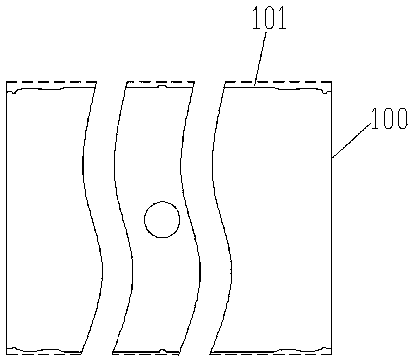
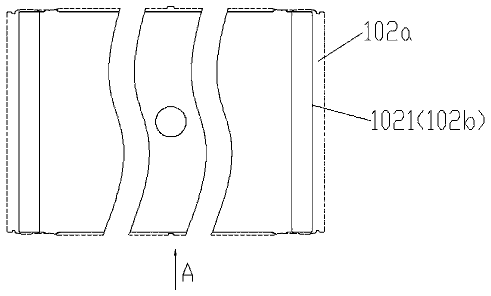
[0045] The production process of the bent plate 100 of this embodiment is as follows: Figure 2-Figure 8 as shown in Figure 9 , Figure 10 As shown, this embodiment provides a bending mechanism, which includes a first slider unit, and the first slider unit includes a first slider 2 that can move along a first direction H, and the first slider unit The slider 2 is used to squeeze the transitional edge 104 of the bent plate 100 so that the transitional edge 104 is bent along a first direction H, and the first direction H is in line with the primary folded edge 102b of the bent plate 100 The bending direction points to the same side of the bent plate 100.

[0046]The bending plate 100 disconnects the primary flange 102b due to the transitional flange 104, so that the peripheral primary flange 102b is not continuous, and the product will not bulge when the secondary be...


PUM


Abstract

The invention provides a bending mechanism, a method for making a bending plate through the bending mechanism and the bending plate. A transition folding edge is arranged on the secondary bending position of the bending plate, when a primary folding edge is bent, the transition bending edge is not bent, the circumferential primary folding edge is broken at the secondary bending position, when thesecondary folding edge is bent, the phenomenon that due to extrusion of the primary bending edge, the crossing position of the secondary bending position and the primary folding edge protrudes outwards is avoided, the non-bent transition folding edge is bent through the bending mechanism, the bending mechanism comprises a first sliding block unit, the first sliding block unit comprises a first sliding block capable of moving in the first direction, the first sliding block moves to extrude the transition folding edge in the first direction to enable the transition folding edge to be bent in thefirst direction, and the first direction and the bending direction of the primary folding edge of the bending plate point to the same side of the bending plate. Accordingly, the technical problem that the product protrudes outwards on the crossing position of the secondary bending position and the primary folding edge is solved while bending of all folding edges of the bending plate is achieved.

Description

technical field [0001] The invention relates to the technical field, in particular to a bending mechanism, a method for making a bent plate by using the bending mechanism and the bent plate. Background technique [0002] At present, sheet metal parts often have a small hem on the bend, that is, a primary hem on the secondary hem. The traditional method is to fold a whole circle of the small hem first, that is, to fold a whole circle of the primary hem first. , and then fold the large bend of the product, that is, fold the secondary edge again, and the product will often bulge outward at the intersection of the bend, such as figure 1 As shown, the position where the secondary bending position 301 meets the primary hem, that is, the position B in the figure bulges outward, and this defect seriously affects the appearance of the product. Contents of the invention [0003] In order to solve the technical problems in the prior art, the present invention provides a bending mech...

Claims


Application Information

Patent Timeline
Patent Type & Authority Applications(China)
IPC IPC(8): B21D5/02
CPCB21D5/0209
Inventor 潘华祥徐建富龙立恒黄树人蔡国旗
Owner ZHUHAI GREE PRECISION MOLD CO LTD
Learn More