Single-phase electricity-to-three-phase electricity conversion power supply device and control method thereof

A power supply device, three-phase power technology, applied in the direction of output power conversion device, circuit device, conversion equipment that can be converted to DC without intermediate conversion, etc., can solve the problems of emergency repair danger, looseness, increase in contact resistance, etc., to achieve Versatility and easy-to-implement effects

A power supply device, three-phase power technology, applied in the direction of output power conversion device, circuit device, conversion equipment that can be converted to DC without intermediate conversion, etc., can solve the problems of emergency repair danger, looseness, increase in contact resistance, etc., to achieve Versatility and easy-to-implement effects

CN110649616APending Publication Date: 2020-01-03SOUTHWEST JIAOTONG UNIV

Image

  • Single-phase electricity-to-three-phase electricity conversion power supply device and control method thereof
  • Single-phase electricity-to-three-phase electricity conversion power supply device and control method thereof
  • Single-phase electricity-to-three-phase electricity conversion power supply device and control method thereof

Examples


Embodiment 1

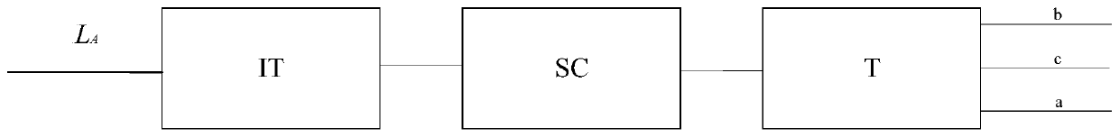
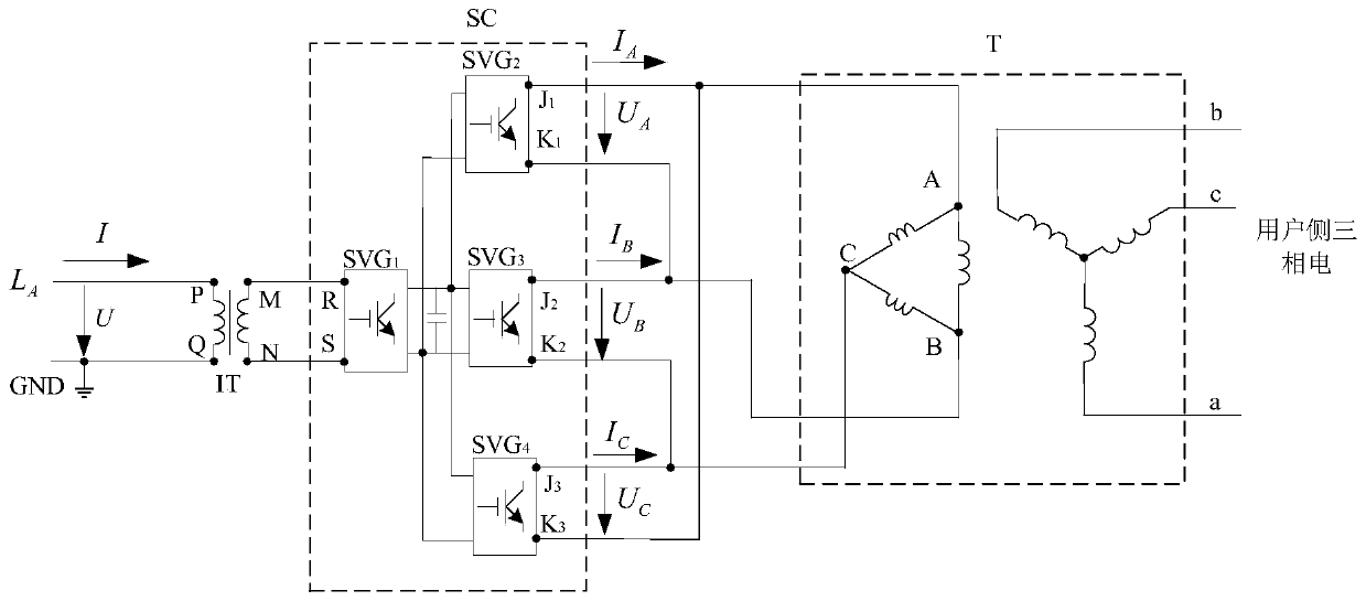
[0027] Such as figure 1 and figure 2 As shown, the embodiment of the present invention provides a single-phase power conversion three-phase power supply device and its control method, including the transmission line L A , isolation transformer IT, power converter SC and three-phase Dyn transformer T; transmission line L A Connect to the P terminal of the IT input end of the isolation transformer, and the Q terminal of the IT input end of the isolation transformer is grounded to GND; the M terminal and the N terminal of the IT output end of the isolation transformer are respectively connected to the R terminal and the S terminal of the SC input end of the power converter in sequence; the power conversion tor SC output J 1 terminal and K 3 The terminals are commonly connected to the A phase of the triangular winding of the three-phase Dyn transformer T, and the K phase of the SC output terminal of the power converter 1 terminal and J 2 The terminals are commonly connected ...

Embodiment 2

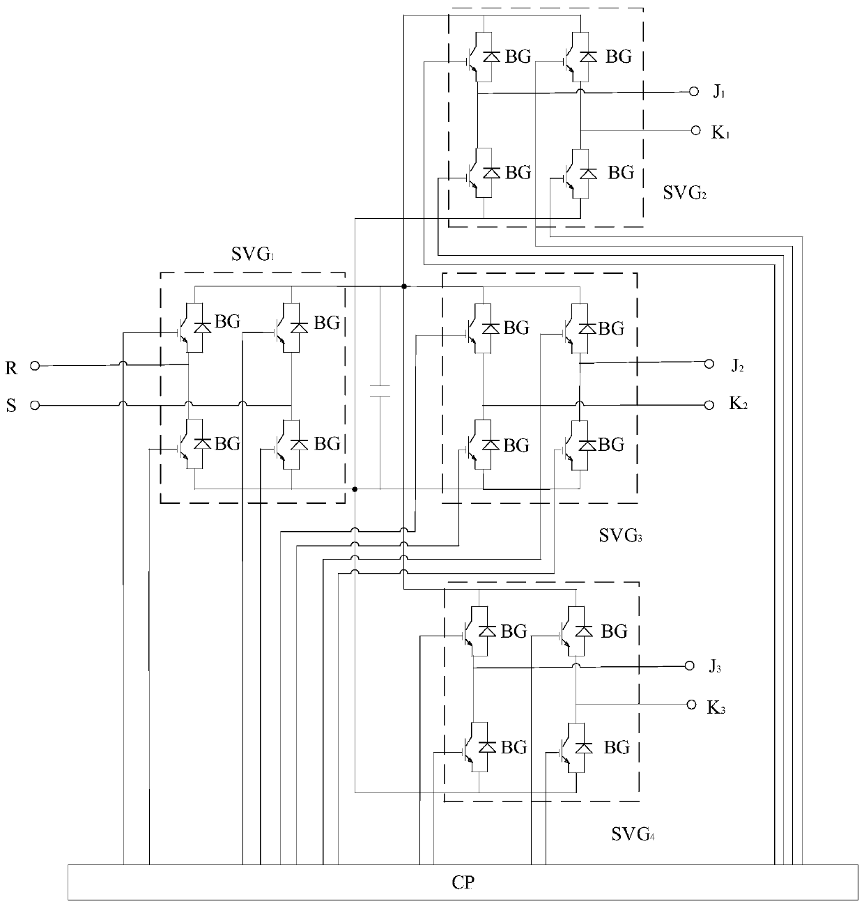
[0033] Such as figure 1 and Figure 4 As shown, the embodiment of the present invention provides a single-phase power conversion three-phase power supply device, including a transmission line L A , isolation transformer IT, power converter SC and three-phase Dyn transformer T; transmission line L A Connect to the P terminal of the IT input end of the isolation transformer, and the Q terminal of the IT input end of the isolation transformer is grounded; the M terminal and the N terminal of the IT output end of the isolation transformer are respectively connected to the R terminal and the S terminal of the SC input end of the power converter; the SC output of the power converter end J 1 terminal and K 3 The terminals are commonly connected to the A phase of the triangular winding of the three-phase Dyn transformer T, and the K phase of the SC output terminal of the power converter 1 terminal and J 2 The terminals are commonly connected to the C phase of the T delta winding ...


PUM


Abstract

The invention discloses a single-phase electricity-to-three-phase electricity conversion power supply device and a control method thereof, and belongs to the technical field of power grid power supplyand distribution. A power transmission line is connected to a terminal P at the input end of an isolation transformer, and a terminal Q at the input end of the isolation transformer is grounded or connected to a return line; a terminal M and a terminal N at the output end of the isolation transformer are respectively connected with a terminal R and a terminal S at the input end of a power converter in sequence; a terminal J1 and a terminal K3 at the output end of the power converter are jointly connected to the phase A of the triangular winding of a three-phase Dyn transformer, a terminal K1and a terminal J2 at the output end of the power converter are jointly connected to the C phase of the triangular winding of the three-phase Dyn transformer, and a terminal K2 and a terminal J3 at theoutput end of the power converter are jointly connected to the phase B of the triangular winding of the three-phase Dyn transformer; and a terminal a, a terminal b and a terminal c at the output endof the star-shaped winding of the three-phase Dyn transformer T are connected with a low-voltage power distribution network with a grounded neutral point.

Description

technical field [0001] The invention relates to the technical field of electric power grid power supply and distribution. Background technique [0002] Users in the field of low-voltage power distribution in my country generally use single-phase power supply. When users need to use three-phase power, they need to re-erect power lines, which is very troublesome and takes a long time; Two-phase transmission lines, three-phase Dyn transformers are connected to users, which is more economical and does not take up space, but some users need three-phase power. In particular, the user needs to use the three-phase power supply for a short period of time due to special reasons, and the time for erecting a new three-phase line is not allowed. If the power quality of the grid allows, the three-phase power supply can be provided relatively easily, which will have a greater impact economic and social value. [0003] In the power distribution system, due to long-term mechanical force, el...

Claims


Application Information

Patent Timeline
03 Jan 2020
Publication
CN110649616A
IPC
H02J3/00; H02J3/18; H02M5/14; H02M5/458
CPC
H02J3/00; H02J3/1842; H02M5/14; H02M5/4585; Y02E40/30
Inventors
易东; 李群湛