
A locomotive without power loopback auxiliary power supply and self-propelled device

An auxiliary power supply and locomotive technology, applied in circuit devices, battery circuit devices, locomotives, etc., can solve problems such as affecting the efficiency of shunting in non-electric areas, lack of self-propelled ability, and easy tripping.

Active Publication Date: 2020-12-22
CHENGDU YUNDA TECH CO LTD
View PDF2 Cites 0 Cited by
  • Summary
  • Abstract
  • Description
  • Claims
  • Application Information

AI Technical Summary

Problems solved by technology

The locomotive has no electricity for a long time, and the crew environment is bad, which indirectly leads to the escort drivers and passengers walking in the dark at night and easily tripping, or when they stop on the way, they cross the line, get under the car, or walk on the track to go to the station to heat up, keep warm or buy food. Even drinking and keeping warm and other violations that bring great risks to personal safety, painful lessons such as personal injuries caused by similar violations are not uncommon.
[0003] At present, the shunting operation in the non-electric area of ​​the locomotive depot is often carried out using shunting machines or diesel locomotives. The procedures for shunting operations are cumbersome and the operation is complicated, which seriously affects the shunting efficiency in the non-electric area. There are certain safety hazards in multi-party cooperation under the car
[0004] The existing published patent application number is 201510462488.4. The technical solution includes a rectifier module connected to the traction motor, a single-phase inverter module, a chopper boost module, a heating component, etc. The output auxiliary power supply only includes AC220V voltage, and It does not have self-propelled ability, which is different from the solution of the present invention

Method used


Image

  • A locomotive without power loopback auxiliary power supply and self-propelled device
  • A locomotive without power loopback auxiliary power supply and self-propelled device
  • A locomotive without power loopback auxiliary power supply and self-propelled device

Examples


Embodiment Construction

[0036] In order to understand the above-mentioned purpose, features and advantages of the present invention more clearly, the present invention will be further described in detail below in conjunction with the accompanying drawings and specific embodiments. It should be noted that, under the condition of not conflicting with each other, the embodiments of the present application and the features in the embodiments can be combined with each other.

[0037] In the following description, many specific details are set forth in order to fully understand the present invention. However, the present invention can also be implemented in other ways different from the scope of this description. Therefore, the protection scope of the present invention is not limited by the following disclosure. limitations of specific examples.

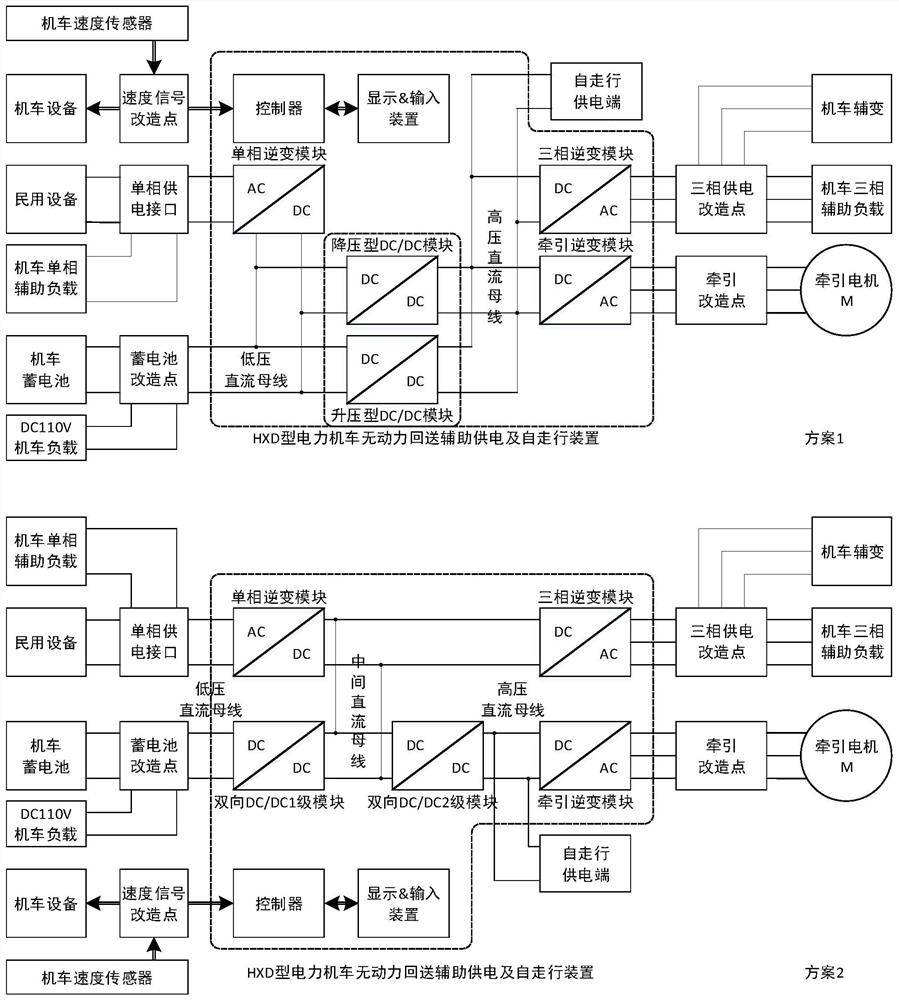
[0038] The invention develops a set of HXD type electric locomotive auxiliary power supply and self-propelled device with no power loopback. This device is used ...


PUM


Abstract

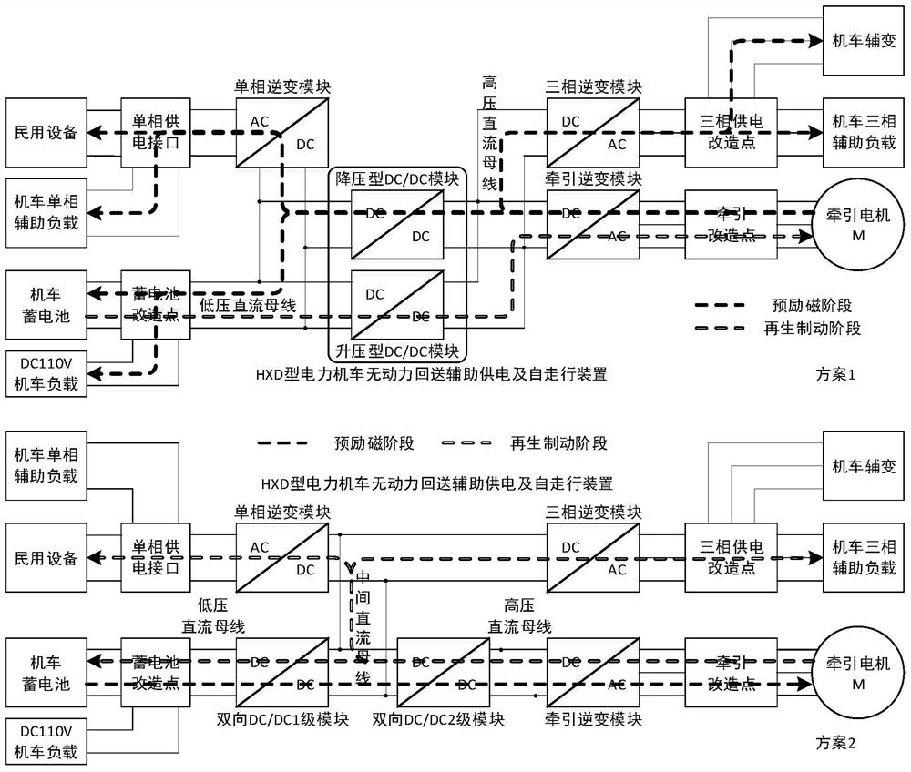
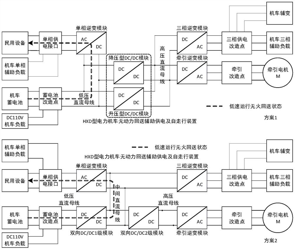
The invention discloses an unpowered loopback auxiliary power supply and self-walking device for locomotives. The device comprises two schemes; in the first scheme, the device comprises a boosting type DC / DC module, a bucking type DC / DC module, a single-phase inverter module, a three-phase inverter module, a traction inverter module and a controller; and in the second scheme, the device comprisesa bidirectional DC / DC primary module, a bidirectional DC / DC secondary module, a single-phase inverter module, a three-phase inverter module, a traction inverter module and a controller. According to the device, a traction motor can be controlled to carry out regenerative braking when being dragged to run, so as to generate power and generate a certain life power supply capacity, so that the operators can watch over on locomotives confidently and securely so as to smoothly complete the locomotive repair / loopback tasks; and DC400V or higher high-power DC power supply can be provided outside thelocomotives to realize shunting operations under speed limiting requirements.

Description

technical field [0001] The invention relates to the field of electric locomotive research, in particular to a locomotive non-power loopback auxiliary power supply and self-propelled device. Background technique [0002] Harmonious high-power AC drive electric locomotive series is the main driving force of railway traction in my country at present. When it is repaired at a higher level such as C4, C5 or C6, it is necessary to provide drivers and passengers from the locomotive attachment section. When the locomotive is completely without electricity, It is escorted to the maintenance base or OEM for repair without fire, and it takes 1 to 7 days on the way. The locomotive has no electricity for a long time, and the crew environment is bad, which indirectly leads to the escort drivers and passengers walking in the dark at night and easily tripping, or when they stop on the way, they cross the line, get under the car, or walk on the track to go to the station to heat up, keep warm...

Claims


Application Information

Patent Timeline
Patent Type & Authority Patents(China)
IPC IPC(8): H02J7/34H02J7/14B61C3/02
CPCY02T10/92Y02T30/00
Inventor 刘川李婷婷崔恒斌王娜夏巧
Owner CHENGDU YUNDA TECH CO LTD
Learn More