Composite magnetic field modulation type magnetic coupling

A magnetic coupling and composite technology, applied in the direction of permanent magnet clutch/brake, electric brake/clutch, electromechanical device, etc., can solve the problems of high speed ratio and instability, and achieve high magnetic field strength, high speed Speed ​​ratio, the effect of increasing the magnetic field strength

Active Publication Date: 2020-01-31
HUAZHONG UNIV OF SCI & TECH
View PDF5 Cites 0 Cited by
  • Summary
  • Abstract
  • Description
  • Claims
  • Application Information

AI Technical Summary

Problems solved by technology

[0005] Aiming at the defects of the prior art, the purpose of the present invention is to provide a composite magnetic field modulation magnetic coupling, aiming at solving the problem that the higher the speed-up ratio of the existing magnetic field modulation magnetic coupling, the more significant the unstable factors are. defect

Method used


Image

  • Composite magnetic field modulation type magnetic coupling
  • Composite magnetic field modulation type magnetic coupling
  • Composite magnetic field modulation type magnetic coupling

Examples


Embodiment Construction

[0028] In order to make the object, technical solution and advantages of the present invention clearer, the present invention will be further described in detail below in conjunction with the accompanying drawings and embodiments. It should be understood that the specific embodiments described here are only used to explain the present invention, not to limit the present invention. In addition, the technical features involved in the various embodiments of the present invention described below can be combined with each other as long as they do not constitute conflicts with each other.

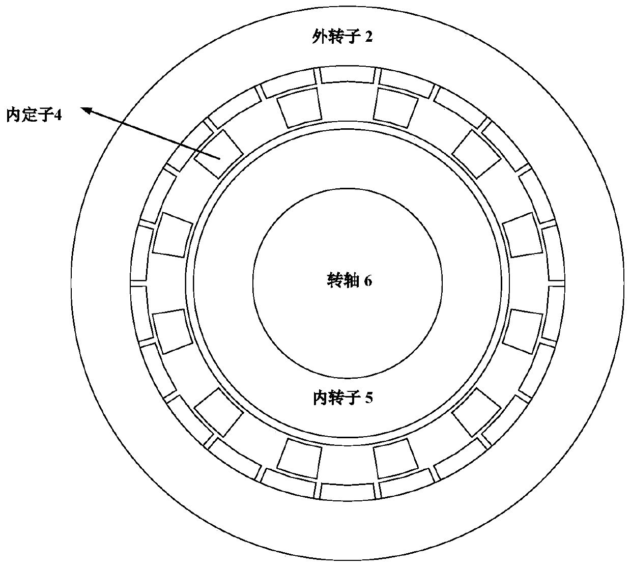
[0029] figure 1 It is a structural schematic diagram of a traditional magnetic field modulation magnetic coupling, including an outer rotor 2 , an inner stator 4 , an inner rotor 5 , and a shaft 6 . All stator and rotor structures are coaxial. The outer rotor 2 is made of magnetically conductive material, and its inner surface is equipped with radially magnetized permanent magnets. The excitati...


PUM


Abstract

The invention discloses a composite magnetic field modulation type magnetic coupling. The magnetic coupling comprises a radial structure and an axial structure; the radial structure comprises two stators and three rotors, wherein the two stators and the three rotors are coaxially arranged in a sleeving mode, and the outer stator, the outer rotor, the middle rotor, the inner stator and the inner rotor are sequentially arranged in a radial direction from outside to inside; permanent magnets are embedded in the inner surface of the outer stator; and a copper ring is arranged on the surface of theinner rotor. The basic working principle of the axial structure is consistent with that of the radial structure; and the axial structure is different from the radial structure in that only a magneticfield direction is changed from radial distribution to axial distribution. With the composite magnetic field modulation type magnetic coupling of the invention adopted, fluctuating low-speed large-torque input can be converted into constant high-speed low-torque output. The composite magnetic field modulation type magnetic coupling is different from an existing structure in that the composite magnetic field modulation type magnetic coupling not only ensures a high speed-up ratio, but also has faster dynamic response, and has a bright application prospect in a wind power generation system.

Description

technical field [0001] The invention belongs to the technical field of permanent magnet motors, and more specifically relates to a composite magnetic field modulation magnetic coupling. Background technique [0002] With the gradual consumption of non-renewable energy, the development of new energy technology has received more and more attention. Wind power, due to its abundant global wind energy reserves, cleanliness and renewability, has been valued by the power industry and applied to the link of power production. In a traditional wind power generation system, a mechanical gearbox is often required to convert the high-torque and low-speed of the wind blades into a high-speed, low-torque output, and then act on the generator; due to the instability of the wind speed, the generator's The speed will fluctuate, which will affect the stability of the power generation frequency. The inverter is required to perform rectification and inversion to obtain electric energy with the ...

Claims


Application Information

Patent Timeline
Patent Type & Authority Applications(China)
IPC IPC(8): H02K49/10
CPCH02K49/106
Inventor 李大伟房莉曲荣海
Owner HUAZHONG UNIV OF SCI & TECH
Why Eureka
Try Eureka