Eureka AIR delivers breakthrough ideas for toughest innovation challenges, trusted by R&D personnel around the world.

Low-fluctuation rare earth permanent magnetic brushless motor

A technology of brushless motors and rare earth permanent magnets, which is applied to the static parts of the magnetic circuit, the rotating parts of the magnetic circuit, the shape/style/structure of the magnetic circuit, etc., can solve the problems of difficult processing and complex structure, and improve the voltage Waveform, reduction of torque ripple, effects of silent operation

Inactive Publication Date: 2008-08-20
GUANGDONG MEIZHI COMPRESSOR
View PDF1 Cites 15 Cited by
  • Summary
  • Abstract
  • Description
  • Claims
  • Application Information

AI Technical Summary

Problems solved by technology

Its structure is more complex and difficult to process

Method used


Image

  • Low-fluctuation rare earth permanent magnetic brushless motor
  • Low-fluctuation rare earth permanent magnetic brushless motor
  • Low-fluctuation rare earth permanent magnetic brushless motor

Examples


Embodiment Construction

[0016] The present invention will be further described below in conjunction with the accompanying drawings and embodiments.

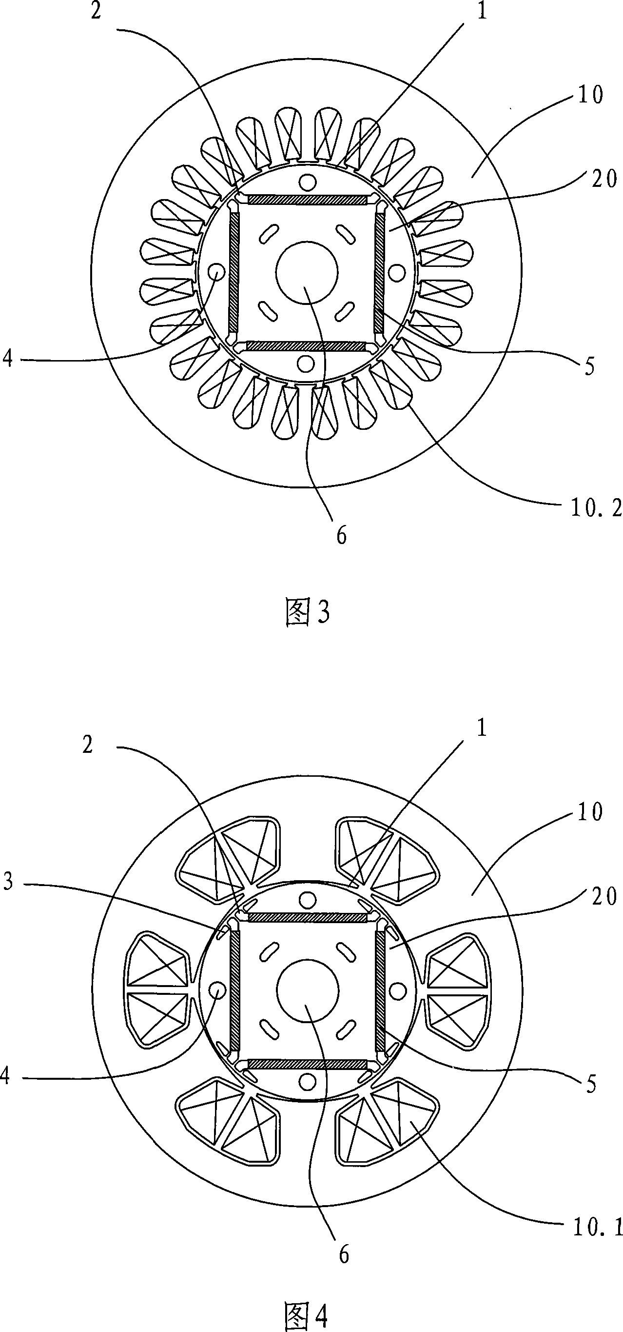
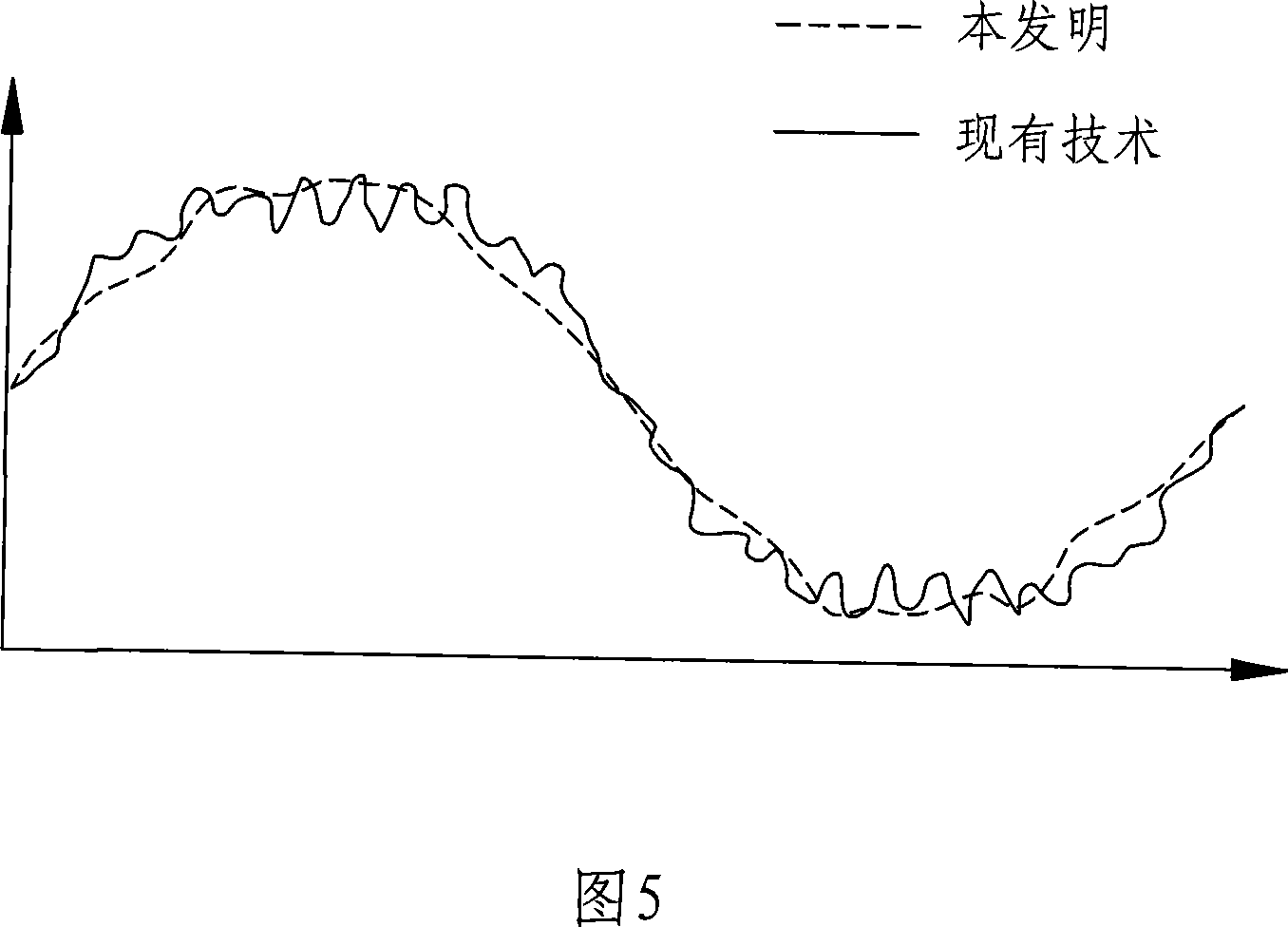
[0017] Referring to Fig. 4-Fig. 5, the low-pulsation rare-earth permanent magnet brushless motor includes a stator 10 and a rotor 20. The rotor is formed into a column by stacking punched sheets. There is a radial air gap 1 between the stator and the rotor. The stator yoke There is a minimum air gap between the outer diameter of the stator and the outer diameter of the rotor, generally 0.1 to 2 mm, and the largest air gap between the slot of the stator and the outer diameter of the rotor, and the largest air gap is 1.5 to 6.0 times the smallest air gap. The six circular arcs on the inner diameter of the stator are located at different centers respectively, and the circular arcs of each segment are evenly distributed along the inner diameter of the stator, wherein the radius of each circular arc is greater than the radius of the rotor punch.

[0018] The...


PUM

PropertyMeasurementUnit
Radiusaaaaaaaaaa

Abstract

A low-pulse rare earth permanent magnetism brushless motor comprises a stator and a rotor which forms a column shape by stacking the punched sheet. A radial air gap is arranged between the stator and the rotor. The rotor is uniformly and symmetrically arranged with a permanent magnet accommodating holes. The permanent magnet is inserted in the accommodating hole and the end of the accommodating hole is arranged with magnetism-splitting holes which are symmetrically arranged at two ends of the diagonal of the accommodating hole. The magnetism-splitting hole is larger at the side next to the accommodating hole and gradually reduces along the radian direction of the outer diameter of the rotor and at last forms a small arc. Through arranging a magnetism-splitting hole at the end of the permanent magnet accommodating hole of the punched piece of the rotor and at the same time designing the radial air gap between the stator and the rotor to asymmetric air gap through the different positions of the inner diameter of the stator and the outer diameter of the rotor, the invention has the advantages of endowing the electric motor with magnetism collecting function, evidently improving the voltage waveform induced in the stator winding, namely improving the back electromotive force waveform of the electric motor, reducing the torque of the tooth socket, reducing the torque ripple, and realizing the high-efficiency, smooth and silent operation of the permanent magnet brushless motor.

Description

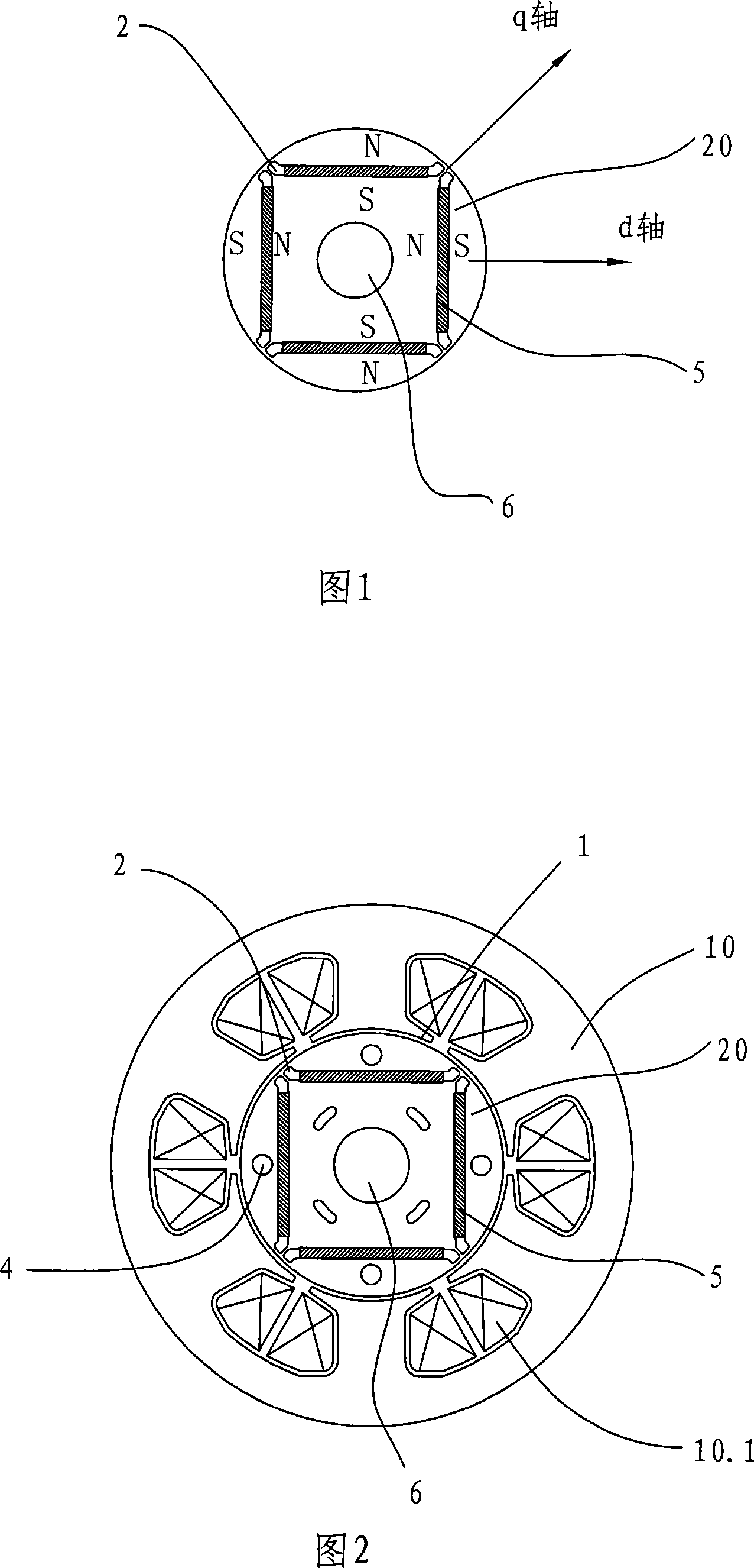
technical field [0001] The invention relates to a permanent magnet motor, in particular to a low-pulsation rare earth permanent magnet brushless motor. Background technique [0002] The rotor iron core of common permanent magnet motors is embedded with ferrite or rare earth permanent magnets. See Figure 1. There is also an air gap in the magnetic circuit of the magnetic flux in the d-axis direction generated by the armature winding. Large magnets with the same reluctance, so the magnetic flux in the q-axis direction can pass through the iron core, and the reluctance in the q-axis direction is reduced. As a result, the inductance Ld<Lq, the motor has the characteristics of a salient pole machine, and the permanent The magnetic motor can increase the reluctance torque to realize the high torque and high efficiency of the permanent magnet motor. Accompanying drawing 2 and accompanying drawing 3 are common typical structures of this permanent magnet motor, wherein: the stato...

Claims


Application Information

Patent Timeline
IPC IPC(8): H02K1/27H02K1/12
Inventor 胡建华
Owner GUANGDONG MEIZHI COMPRESSOR
Why Eureka
Eureka Blog
Learn More