Supercharge Your Innovation With Domain-Expert AI Agents!

Self-acting pressure drain valve

一种排放阀、压力的技术,应用在隔膜阀、控制阀、平衡阀等方向

Active Publication Date: 2020-04-17
HAMILTON SUNDSTRAND CORP
View PDF6 Cites 0 Cited by
  • Summary
  • Abstract
  • Description
  • Claims
  • Application Information

AI Technical Summary

Problems solved by technology

However, when the borehole is sized too small, debris (eg, dust, dirt, etc.) can clog the hole and prevent water from draining properly from the ECS

Method used


Image

  • Self-acting pressure drain valve
  • Self-acting pressure drain valve
  • Self-acting pressure drain valve

Examples


Embodiment Construction

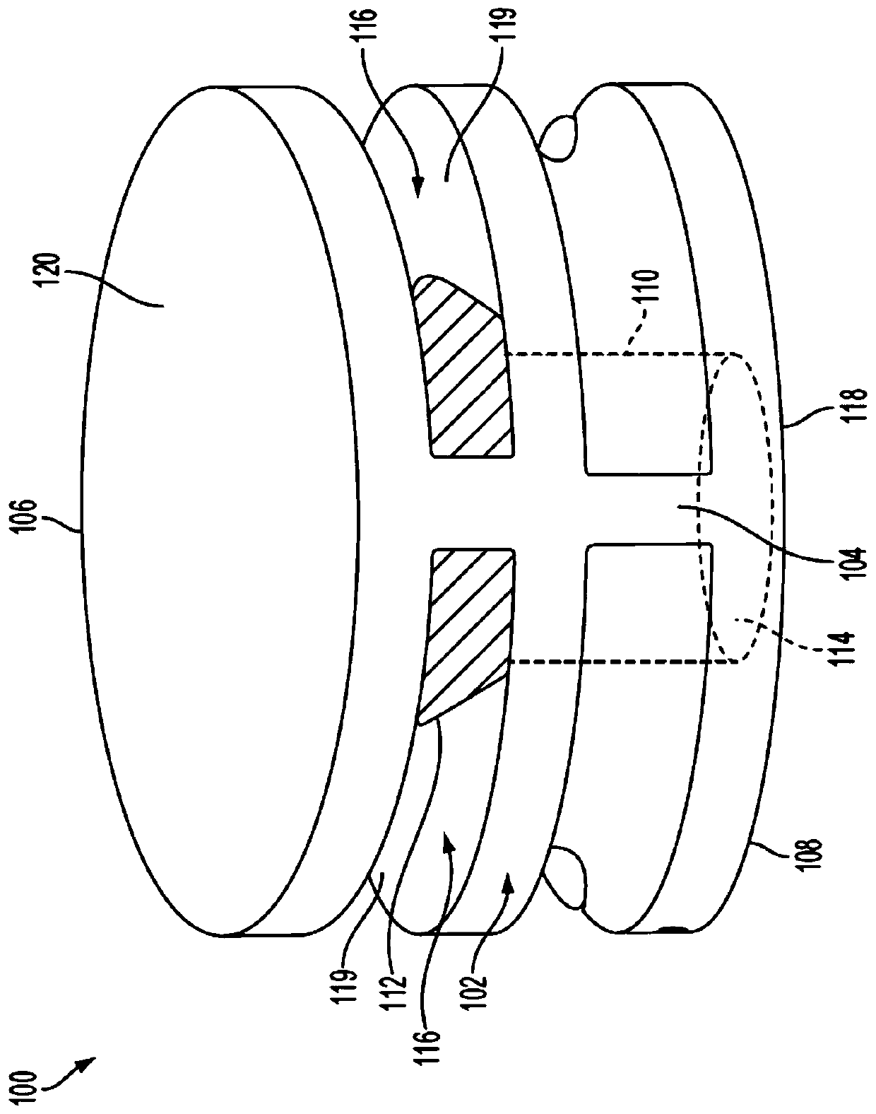
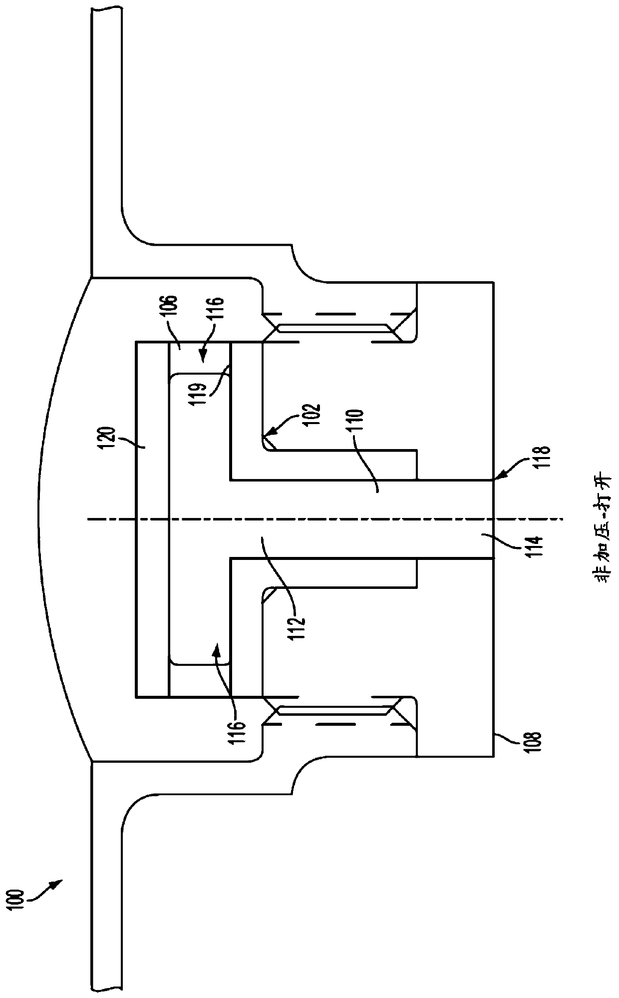
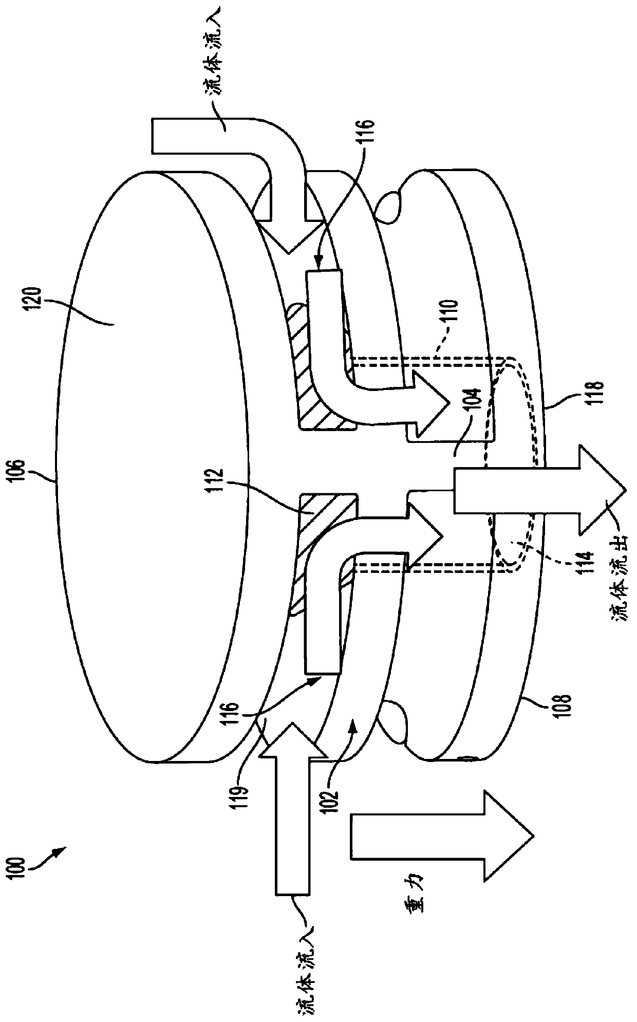
[0017] Various non-limiting embodiments of the present invention provide an automatic pressure relief valve that does not require active control or input from a microcontroller and / or individual actuators. An automatic pressure relief valve can be placed in the system which changes the ambient pressure based on whether the system is operating or shut down. When the system is shut off (ie, not in operation), the automatic pressure drain valve is normally biased into an open position so that fluid (eg, water) can be drained through the valve's drain passage. However, when the system is operating (ie, open), the increased pressure induces the valve into the closed position. Accordingly, the discharge channel is sealed such that air leakage through the discharge channel is prevented. In this way, pressure within the ECS is maintained and overall efficiency is improved. Because the vent channel can be selectively closed, the diameter of the vent channel can be sized larger than c...


PUM


Abstract

A self-acting pressure drain valve includes at least one inlet configured to receive a fluid. A drainage passage delivers the fluid to at least one outlet where the fluid is expelled. The self-actingpressure drain valve further includes a flexible diaphragm configured to operate at an open position and a closed position based on the pressure. The flexible diaphragm is normally biased at the openposition such that the fluid is delivered from the at least one inlet to the at least one outlet via the drainage passage. The pressure, however, initiates the closed position such that air is prevented from flowing through the drainage passage.

Description

technical field [0001] The present invention relates generally to fluid discharge valves and, more particularly, to an automatic pressure activated discharge valve. Background technique [0002] Vehicles such as, for example, commercial airline vehicles include environmental control systems (ECS) that operate to control pressure and environmental conditions for improved passenger and crew comfort. When the ECS is switched off and exposed to cool and humid ambient air conditions, the temperature difference between the ECS and the ambient air may cause water condensation, which after a period of time leads to water accumulation at one or more locations of the ECS (i.e. , stagnant water). [0003] Conventional methods for preventing standing water include drilling holes in various locations of the ECS where water typically accumulates. Although the boreholes allow water to drain, the holes remain open regardless of whether the ECS is operating or shut down. As a result, the ...

Claims


Application Information

Patent Timeline
Patent Type & Authority Applications(China)
IPC IPC(8): F16K31/126F16K27/02
CPCF16K31/126F16K27/0236F16K15/144F16K15/16F16K17/28Y10T137/7869F16K31/1266F16K7/00F16K21/00
Inventor C.麦考利费N.帕尔默
Owner HAMILTON SUNDSTRAND CORP
Features
  • R&D
  • Intellectual Property
  • Life Sciences
  • Materials
  • Tech Scout
  • Unparalleled Data Quality
  • Higher Quality Content
  • 60% Fewer Hallucinations
Learn More