
Multi-oil-cylinder cooperative compression compensation system for garbage compressor

A garbage compressor and compensation system technology, applied in mechanical equipment, fluid pressure actuating devices, servo motor components, etc., can solve the problem of pressure head stuck, large size changes of garbage blocks, and garbage easily falling behind the pressure head and other problems to achieve the effect of reducing the sticking of the indenter and making the molding dimension stable and accurate.

Active Publication Date: 2020-06-05
长沙普惠环保机械有限公司
View PDF10 Cites 0 Cited by
  • Summary
  • Abstract
  • Description
  • Claims
  • Application Information

AI Technical Summary

Problems solved by technology

[0004] Based on this, the present invention proposes a multi-cylinder cooperative compression compensation system for garbage compressors. The size of the rubbish block produced in the process changes greatly, the pressure head is stuck, and the garbage is easy to fall at the back of the pressure head.

Method used


Image

  • Multi-oil-cylinder cooperative compression compensation system for garbage compressor
  • Multi-oil-cylinder cooperative compression compensation system for garbage compressor

Examples


Embodiment Construction

[0025] In order to make the above objects, features and advantages of the present invention more comprehensible, specific implementations of the present invention will be described in detail below in conjunction with the accompanying drawings. In the following description, numerous specific details are set forth in order to provide a thorough understanding of the present invention. However, the present invention can be implemented in many other ways different from those described here, and those skilled in the art can make similar improvements without departing from the connotation of the present invention, so the present invention is not limited by the specific implementations disclosed below.

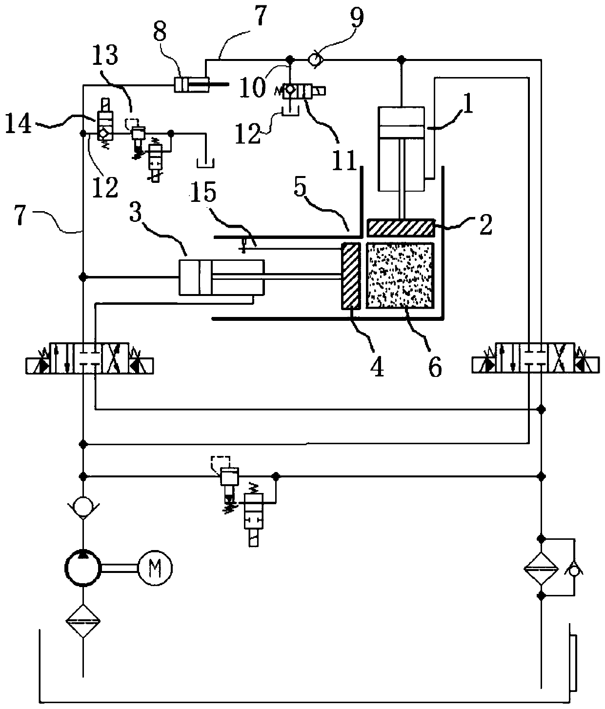
[0026] see figure 2 , the present invention provides a multi-cylinder cooperative compression compensation system for garbage compressors, which includes a compression chamber 5, a first compression cylinder 1 and a second compression cylinder 3, and the end of the piston rod of the ...


PUM


Abstract

The invention discloses a multi-oil-cylinder cooperative compression compensation system for a garbage compressor. The multi-oil-cylinder cooperative compression compensation system comprises a compression bin, a first compression oil cylinder and a second compression oil cylinder, the end of a piston rod of the first compression oil cylinder is connected with a first pressing head, and the end ofa piston rod of the second compression oil cylinder is connected with a second pressing head capable of acting on garbage blocks together with the first pressing head; the multi-oil-cylinder cooperative compression compensation system for the garbage compressor further comprises a pressure compensation oil way connected between a rodless cavity of the first compression oil cylinder and a rodlesscavity of the second compression oil cylinder, a pressure compensation oil cylinder is arranged on the pressure compensation oil way, and the rodless cavity of the pressure compensation oil cylinder is connected with the rodless cavity of the second compression oil cylinder; and a rod cavity of the pressure compensation oil cylinder is connected with the rodless cavity of the first compression oilcylinder. The system aims at solving the technical problems that in the prior art, in the actual working process of a multi-oil-cylinder system of the garbage compressor, the size change of generatedgarbage blocks is large, the pressing heads are clamped, and garbage is likely to fall to the rear portions of the pressing heads.

Description

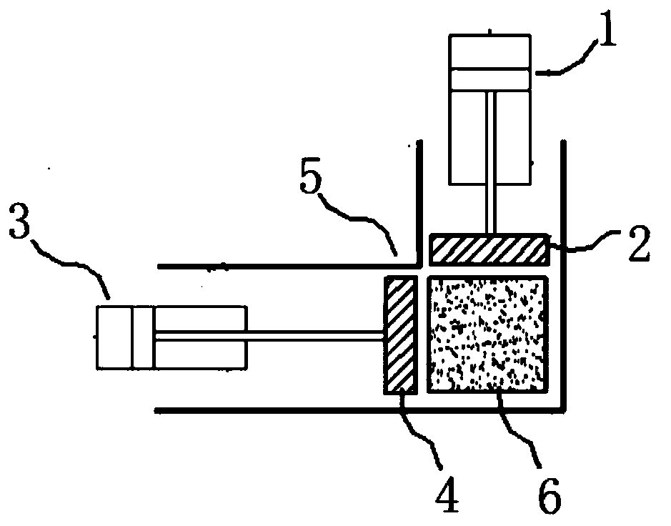
technical field [0001] The invention relates to the field of hydraulic systems of garbage compressors, in particular to a multi-cylinder cooperative compression compensation system for garbage compressors. Background technique [0002] see figure 1 The main components of the multi-cylinder system of the garbage compressor shown in the prior art include a first compression cylinder 1 and a second compression cylinder 3, the end of the piston rod of the first compression cylinder 1 is connected to the first pressure head 2, The end of the piston rod of the second compression oil cylinder 3 is connected with the second ram 4, and when the first ram 2 compresses the rubbish block 6 in the compression bin 5 from the first direction (for example, vertically), the rubbish block 6 will A reverse thrust force is generated on the second pressure head 4, so that the second pressure head 4 retreats in the second direction (for example, laterally). When the first pressure head 2 cancels...

Claims


Application Information

Patent Timeline
IPC IPC(8): F15B15/20F15B13/06F15B15/28
CPCF15B15/20F15B13/06F15B15/2846
Inventor 刘湘
Owner 长沙普惠环保机械有限公司
Learn More