Inverter and control method thereof

An inverter and inverter circuit technology, applied in control/regulation systems, instruments, regulating electrical variables, etc., can solve the problems of poor resistance to load disturbance, large size, and low efficiency of the output voltage of the inverter

CN111262469AInactive Publication Date: 2020-06-09CRRC QINGDAO SIFANG ROLLING STOCK RES INST
5 Cites 2 Cited by

Patent Information

Authority / Receiving Office
CN · China
Current Assignee / Owner
Publication Date
2020-06-09
Estimated Expiration
Not applicable · inactive patent

Smart Images

  • Figure 1
    Figure 1
  • Figure 2
    Figure 2
  • Figure 3
    Figure 3
Patent Text Reader

Abstract

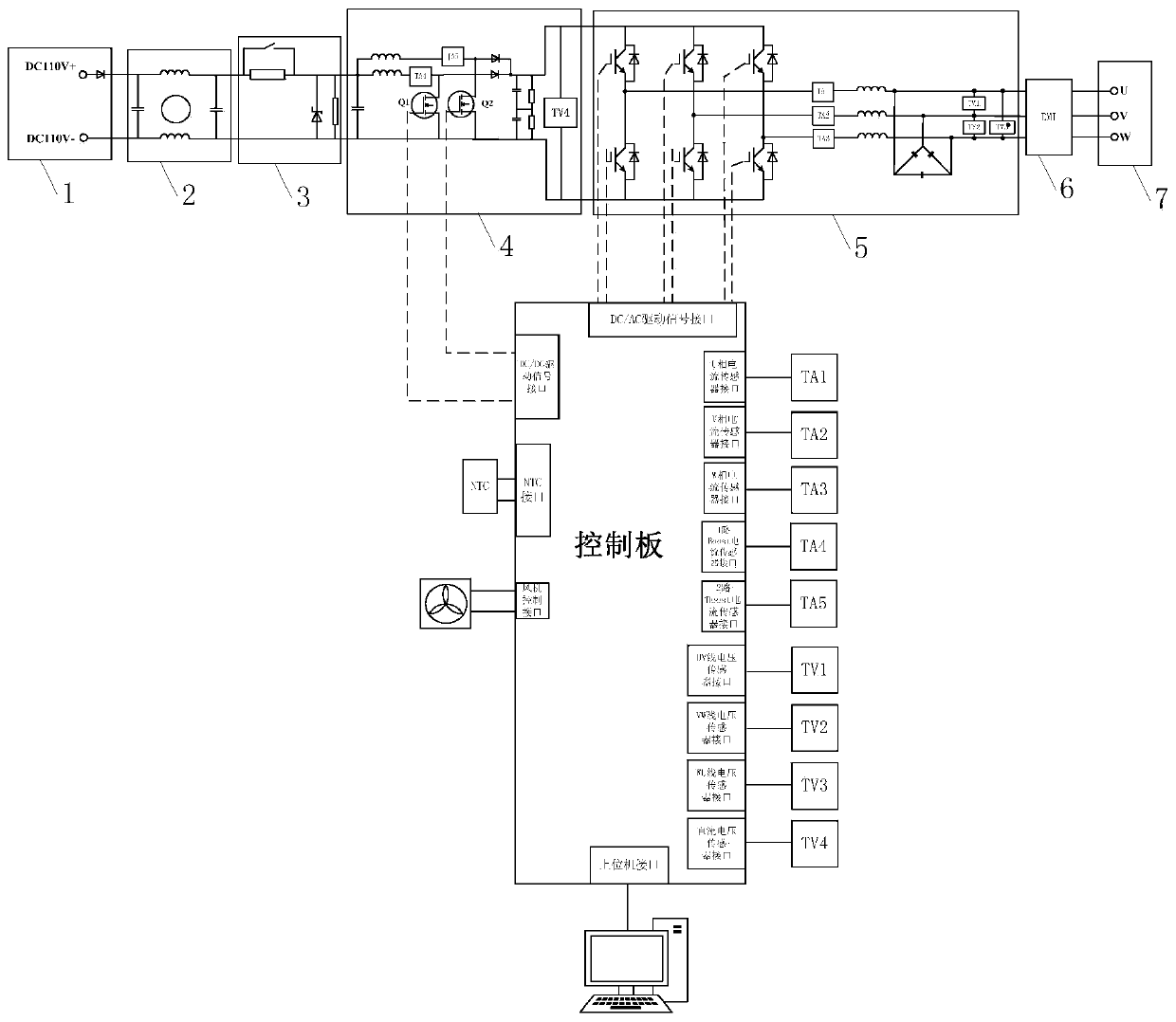
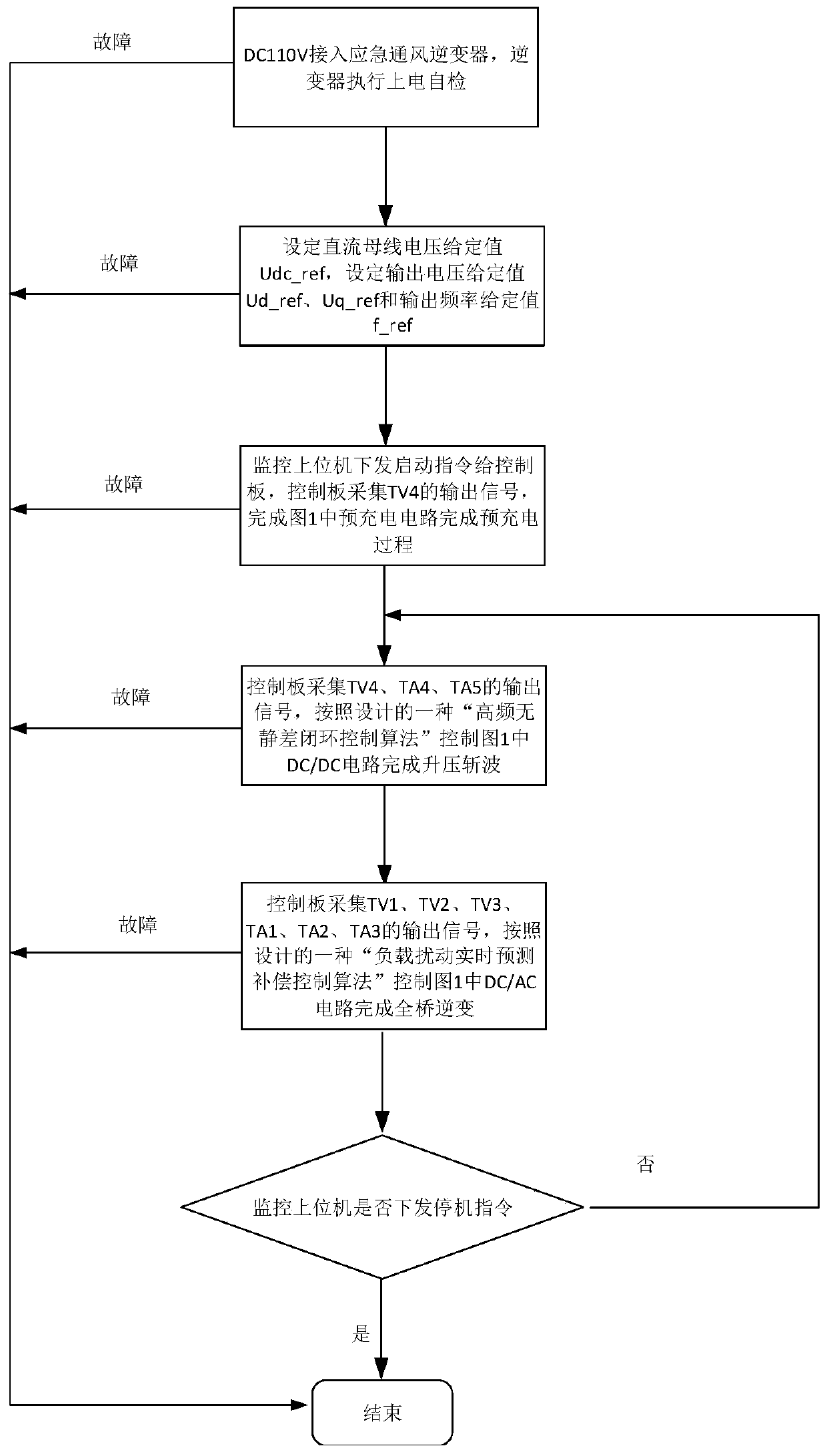
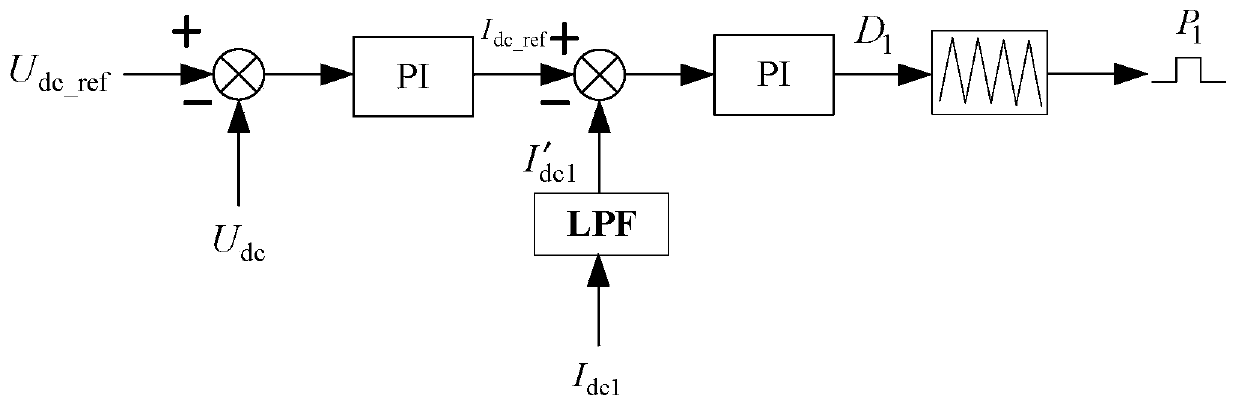
The invention provides an inverter and a control method thereof. The inverter is characterized in that a DC / DC circuit comprises a first boosting branch and a second boosting branch which are connected in parallel; and switching pieces in the first boosting branch and the second boosting branch are controlled by a controller. The configuration and control method of the controller are as follows: afirst voltage outer loop adjusting unit is configured to calculate and output a direct-current bus current expected value according to a direct-current bus voltage expected value and a direct-currentbus voltage real-time value; a first current inner loop adjusting unit is configured to calculate and output a control signal of the first boosting branch according to a direct-current bus current expected value and the chopping current of the first boosting branch; and a second current inner loop adjusting unit is configured to calculate and output a control signal of the second boosting branchaccording to the direct-current bus current expected value and chopping current of the second boosting branch. The DC / DC circuit of the inverter system adopts a double-path parallel boost chopper circuit, so that the high boost transformation ratio of the inverter under low-voltage input can be realized, and the low-voltage loading capacity of the inverter is improved.
Need to check novelty before this filing date? Find Prior Art

Description

technical field

[0001] The invention relates to the technical field of power electronics, in particular to an inverter and a control method for the inverter. Background technique

[0002] The inverter is the core component of the power supply system.

[0003] According to the change of power supply demand, the requirements for the load capacity, anti-interference performance and stability of the inverter are constantly increasing. Taking the train emergency ventilation system as an example, the inverter is used to supply power to the fan inside the air conditioner outside the train when the power supply failure of the subway vehicle occurs. In an emergency state, the inverter system needs to make a timely and stable response. In terms of hardware structure, traditional inverters generally have poor load performance under low-voltage input, cannot achieve high-efficiency load operation, and the inverter output voltage has poor anti-load disturbance performance. Low-level d...

Examples

Embodiment Construction

[0076] In order to make the technical problems, technical solutions and beneficial effects to be solved by the present invention clearer, the present invention will be further described in detail below in conjunction with the accompanying drawings and embodiments. It should be understood that the specific embodiments described here are only used to explain the present invention, not to limit the present invention.

[0077] It should be noted that the terms "first", "second", "third", and "fourth" are used for descriptive purposes only, and are not used to imply relative importance.

[0078] In some embodiments of the present invention, an inverter is firstly provided, and the structure refers to figure 1 ,include:

[0079] Main circuit: including DC / DC circuit 4 and inverter circuit 5, the input end of the DC / DC circuit is connected to a power supply, specifically DC110V DC power supply, the output end is connected to the inverter circuit, and the output end of the inverter c...