A functional part, a bonding jig and a bonding method

A technology for laminating fixtures and functional parts, applied in chemical instruments and methods, lamination, lamination devices, etc., can solve the problems of lamination bubbles, lamination cracks, etc.

Active Publication Date: 2022-07-22
BOE TECH GRP CO LTD +1
View PDF0 Cites 0 Cited by
  • Summary
  • Abstract
  • Description
  • Claims
  • Application Information

AI Technical Summary

Problems solved by technology

For the display screens with larger bending angles that appear now, if the bonding between the display screen and the glass cover is completed in the way of the prior art, problems such as bonding bubbles and bonding cracks are prone to occur

Method used


Image

  • A functional part, a bonding jig and a bonding method
  • A functional part, a bonding jig and a bonding method
  • A functional part, a bonding jig and a bonding method

Examples


Embodiment Construction

[0033] The technical solutions in the embodiments of the present application will be clearly and completely described below with reference to the accompanying drawings in the embodiments of the present application. Obviously, the described embodiments are part of the embodiments of the present invention, but not all of the embodiments. Based on the embodiments of the present invention, all other embodiments obtained by those of ordinary skill in the art without creative efforts shall fall within the protection scope of the present invention.

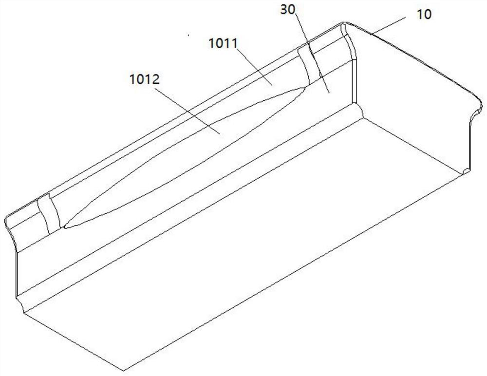
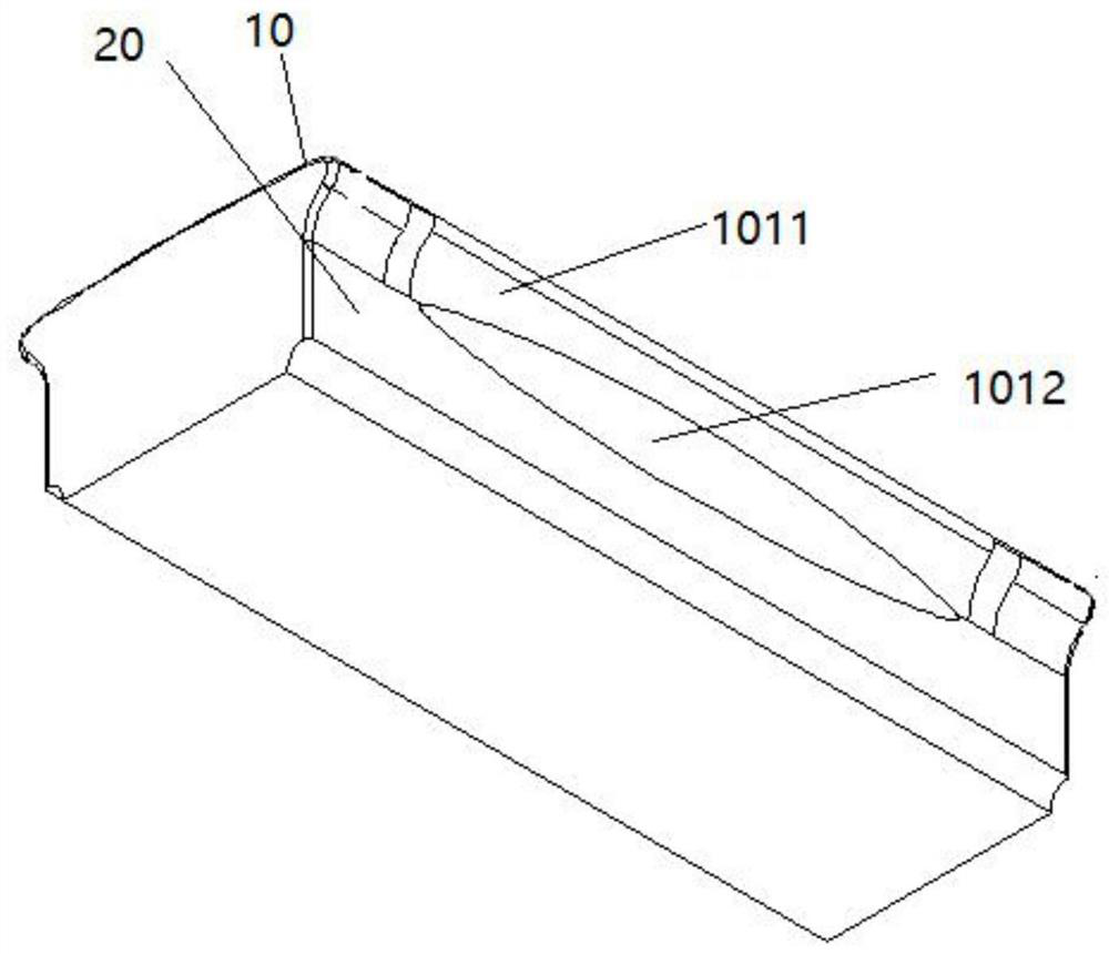
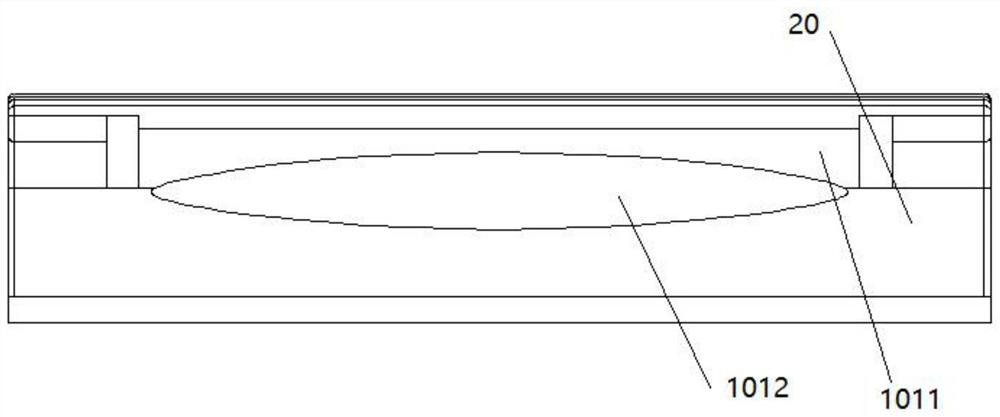
[0034] The embodiment of the present application discloses a functional component, refer to Figure 1-Figure 6 , the functional piece is applied in the lamination fixture, the functional piece includes a target surface 10, and the target surface 10 has a first profiling surface for fitting with the piece to be laminated; the target surface 10 It includes a first curved surface 101, a second curved surface 102 and a third curved surface 1...


PUM


Abstract

The embodiment of the present application discloses a functional piece, a fitting jig and a fitting method. The functional piece includes a target surface, and the target surface has a first profiling surface for fitting with the piece to be fitted; the target surface It includes a first curved surface, a second curved surface and a third curved surface that are smoothly connected in sequence, wherein the first curved surface and the third curved surface are located on both sides of the second curved surface and extend toward a first direction; the first direction is the first curved surface. The curved surface or the third curved surface is away from the direction of the second curved surface; both the first curved surface and the third curved surface are provided with concave contour grooves extending along a second direction, and the second direction is perpendicular to the first direction. The embodiment of the present application can reduce the pressure and pulling force of the edge region of the to-be-laminated part in the process of using the functional part to attach the to-be-laminated part, and can also reduce the expansion amount of the middle part of the functional part and slow down the lamination of the to-be-laminated part. The lamination speed from the middle to both sides during the process, so as to avoid the problems of lamination bubbles and lamination cracks.

Description

technical field [0001] The present invention relates to the technical field of display screens, in particular to a functional component, a laminating jig and a laminating method. Background technique [0002] At present, as the manufacturing process of flexible display screens becomes more and more mature, in order to improve the technological type and modernity of the display device, the requirements for the bending angle of the display screen are getting higher and higher. [0003] Most of the bending angles of the existing flexible screens are within 90°, and the existing technology can only solve the bonding between the display screen and the glass cover at 0°-90°. For the display screen with a larger bending angle that appears now, if the bonding between the display screen and the glass cover plate is also completed by means of the prior art, problems such as bonding bubbles and bonding cracks are prone to occur. SUMMARY OF THE INVENTION [0004] In view of the above...

Claims


Application Information

Patent Timeline
Patent Type & Authority Patents(China)
IPC IPC(8): B32B37/00
CPCB32B37/003
Inventor 张帅田雨魏东崔洪伟王康康赵庆
Owner BOE TECH GRP CO LTD
Why Eureka
Try Eureka