Display device

A display device and display panel technology, applied in light guides, optics, instruments, etc., can solve the problems of dark bands in the display area of ​​the display panel, poor display effect of the display device, etc., achieve good display effect, reduce dark band phenomenon, and simple structure Effect

Inactive Publication Date: 2020-07-14
HISENSE VISUAL TECH CO LTD
View PDF13 Cites 4 Cited by
  • Summary
  • Abstract
  • Description
  • Claims
  • Application Information

AI Technical Summary

Problems solved by technology

[0004] However, for a display panel with an extremely narrow BM area, due to the narrow black border area, the above-mentioned structural components can easily enter into the area corresponding to the d...

Method used


Image

  • Display device
  • Display device
  • Display device

Examples


Embodiment 1

[0050] In this embodiment, the display device 100 adopts an edge-lit backlight module 10 .

[0051]

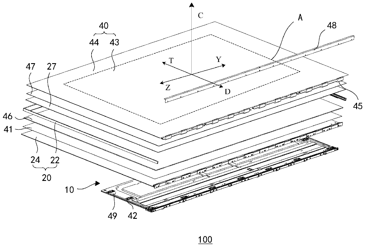
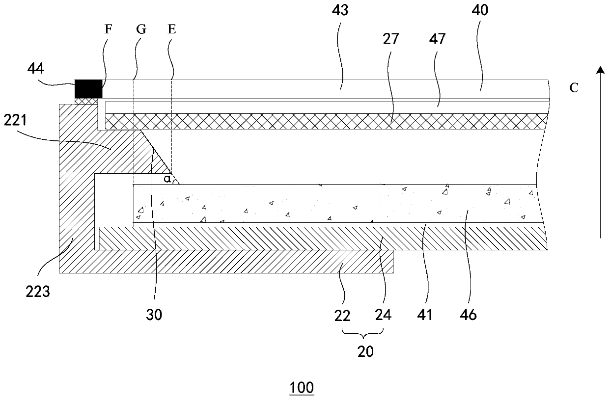
[0052] figure 1 It is a schematic diagram of an exploded structure of the display device 100 provided in Embodiment 1 of the present invention, figure 2 It is a schematic cross-sectional structure diagram of the display device 100 provided by Embodiment 1 of the present invention.

[0053] refer to figure 1 , the display device 100 includes a backlight module 10 and a display panel 40 , and the backlight module 10 is used to provide a backlight for the display panel 40 .

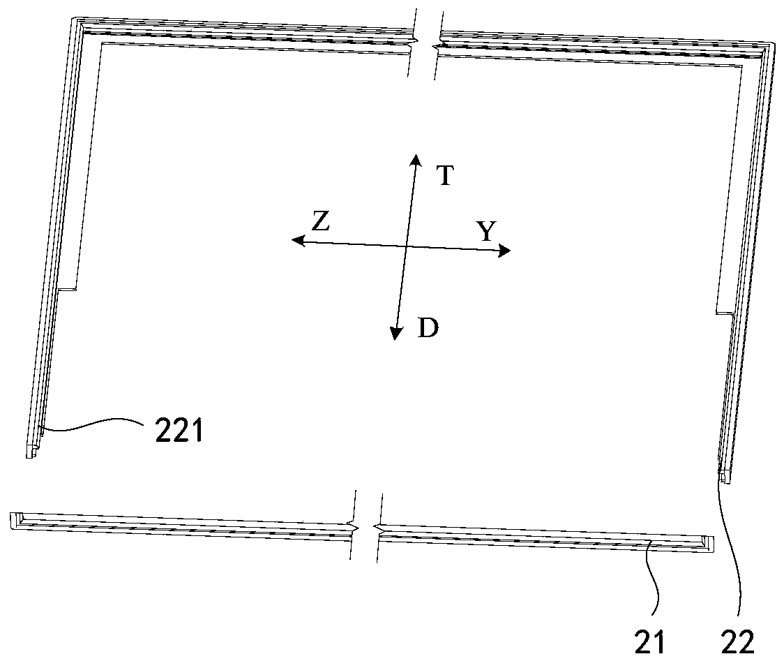
[0054] The backlight module 10 includes a supporting and fixing component 20 and at least two layers of optical film materials. In the edge-lit backlight module 10, the at least two layers of optical film materials may include reflective sheets 41, light guide plates 46, diffuser plates 27, and the like.

[0055] In this application, the diffusion plate 27 specifically refers to a layer that uniformly ...

Embodiment 2

[0164] This embodiment is similar to the first embodiment, except that the display device 200 of this embodiment uses a direct-lit backlight module 50 .

[0165]

[0166] Figure 11 It is a schematic cross-sectional structure diagram of a display device 200 with another structure provided in Embodiment 2 of the present invention, refer to Figure 11 , the display device 200 includes a backlight module 50 and a display panel 40, and the backlight module 50 is used to provide a backlight for the display panel.

[0167] The backlight module 50 may include a supporting and fixing component 60 and at least two layers of optical film materials. In the direct-type backlight module 50 , the optical film materials may include: a reflection sheet 55 , a diffusion plate 52 and the like.

[0168] In this application, the diffusion plate 52 specifically refers to a layer that uniformly and diffuses light.

[0169] In this application, the optical film 51 attached to the upper surface o...


PUM

PropertyMeasurementUnit
Vertical distanceaaaaaaaaaa

Abstract

The invention provides a display device. The display device comprises a display panel and a backlight module, the backlight module is used for providing a backlight source for the display panel, and the backlight module comprises a light source; the light source is located on the side of the light guide plate, and the light guide plate is used for converting light emitted by the light source intoan area source; the diffusion plate is used for homogenizing the light emitted by the light guide plate. Via the display device disclosed in the invention, the display effect is excellent even for thedisplay panel with an extremely narrow BM area.

Description

technical field [0001] The present invention relates to the field of display technology, in particular to a display device. Background technique [0002] With the development of modern industry and the increasingly fierce competition in the semiconductor industry, the market for display devices with liquid crystal display panels is rapidly expanding. [0003] Currently, a display device using a liquid crystal display panel also includes a backlight module for providing a backlight source for the display panel. The display panel includes a display area and a black border area (Black Matrix, BM) surrounding the display area. The backlight module usually includes structural components protruding into the display area of ​​the display panel when viewed from above, and the protruding parts of these structural components into the display area will cause defects such as dark shadows in the display area. Usually, in order not to affect the normal display of the display panel, thes...

Claims


Application Information

Patent Timeline
IPC IPC(8): G02F1/13357G02B6/00
CPCG02B6/0051G02F1/133606G02F1/133611G02F1/133615
Inventor 唐志强石磊陈宇
Owner HISENSE VISUAL TECH CO LTD
Why Eureka
Try Eureka