Unlock instant, AI-driven research and patent intelligence for your innovation.
Negative pressure type air purifying lift car
What is Al technical title?
Al technical title is built by PatSnap Al team. It summarizes the technical point description of the patent document.
An air purification and negative pressure technology, which is applied in the field of elevator cars, can solve the problems of inability to purify the air efficiently, incapable of rapid ventilation, cross-infection of passengers in the car, etc.
Pending Publication Date: 2020-08-21
SHANGHAI MITSUBISHI ELEVATOR CO LTD
View PDF7 Cites 9 Cited by
Summary
Abstract
Description
Claims
Application Information
AI Technical Summary
This helps you quickly interpret patents by identifying the three key elements:
Problems solved by technology
Method used
Benefits of technology
Problems solved by technology
[0009] The technical problem to be solved by the present invention is to overcome the above-mentioned deficiencies of the prior art and provide a negative-pressure air-purifying car. The negative pressure inside the car can solve the problem that the air cannot be exchanged quickly between the car and the shaft or waiting hall. , The air in the car and the shaft cannot be efficiently purified, leading to technical problems such as the risk of cross-infection of the car occupants
Method used
Image
Click on the blue label to locate the original text in one second.
Reading with bidirectional positioning of images and text.
Examples
no. 1 example
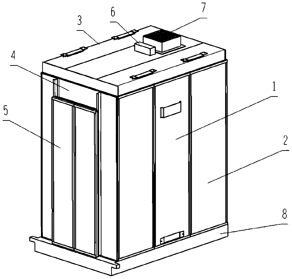
[0147] See figure 1 , The present invention provides a negative pressure type air purification car, which is characterized by comprising:
[0148] The car door (5), the car door (5) is arranged on the first side of the air purification car, and the upper door (4) is provided above the car door (5);
[0149] A plurality of car walls (2) are arranged on the first side, the second side, the third side and the fourth side of the air purification car;
[0150] The car walls (2) on the first side are respectively located on both sides of the car door (5) and the upper board (4) of the entrance and exit;
[0151] The upper end of the car wall (2) is connected with the car top (3), and the lower end of the car wall (2) is connected with the car bottom (8);
[0152] At least one first vent is provided at the lower part of the car wall (2) not arranged on the first side;
[0153] A negative pressure fan (7) and a control device are provided on the car top (3);
[0154] The control device is electri...
no. 2 example
[0301] On the basis of the first embodiment, this embodiment provides a negative pressure type air purification car with a simpler structure and a more uniform and stable ventilation flow.
[0302] Such as Figure 8 As shown, in this embodiment, on the basis of the first embodiment, the car bottom (8) on the second side, the third side and the fourth side is provided with a car bottom skirting seat (42), and a car wall (2). The lower end of) is installed on the car bottom skirting board seat (42) and there is a ventilation gap between the car bottom skirting board seat (42), and the first vent is formed by the ventilation gap.
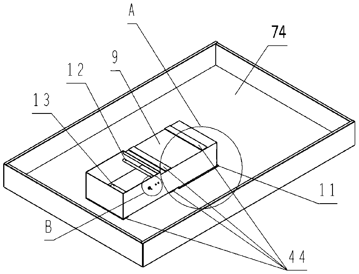
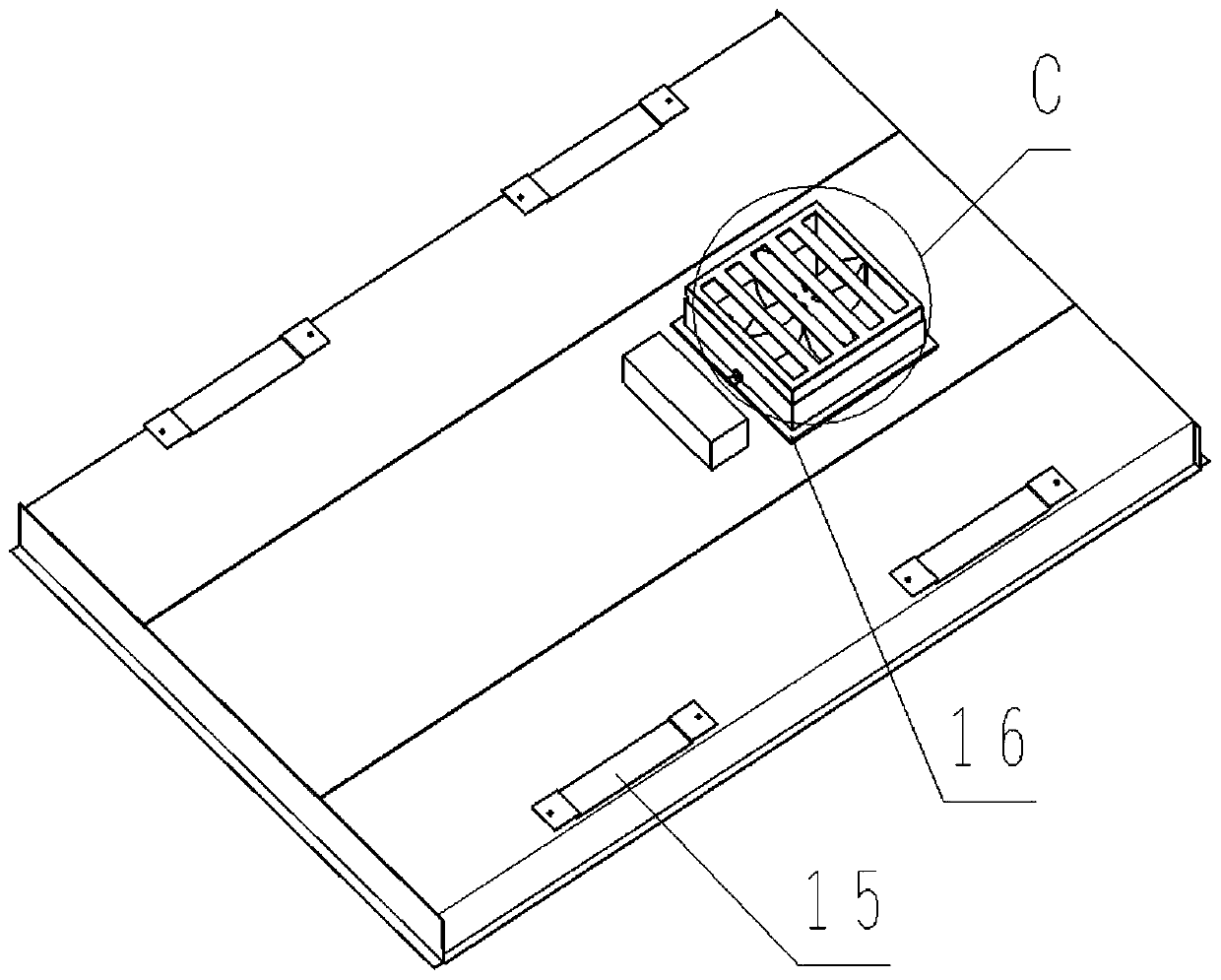
[0303] In this embodiment, the car top (3) does not have the third automatic ventilation opening and closing device (15), which makes the structure simpler. Such as Picture 9 As shown, the area on the ceiling plate (74) that does not overlap the negative pressure box (9) is no longer provided with ceiling vents, and there is no need to set up louvers (38) ...
no. 3 example
[0308] This embodiment is based on the second embodiment to provide a negative pressure air purification car with a simpler structure and a more uniform and stable ventilation airflow.
[0309] Such as Picture 10 In this embodiment, on the basis of the second embodiment, the present invention provides a negative pressure type air purification car, further eliminating the second automatic ventilation opening and closing device at the bottom of the negative pressure box (9) ( 13), making the structure simpler and electrical control more convenient. The implementation principle of this embodiment is as follows:
[0310] When the car door (5) is opened, the negative pressure of the internal air of the air purification car is smaller than that of the outside air, and the air flow velocity flowing to the air purification car in the waiting hall is smaller than that of the second embodiment, which is suitable for elevators In occasions with low traffic.
PUM
Abstract
The invention provides a negative pressure type air purifying lift car. At least one first ventilation opening is formed in the lower portion of a car wall, and a negative pressure type fan is arranged on a car top or a fourth ventilation opening is formed in the car top. The negative pressure type fan (7) is arranged at the lower portion of the car wall (2), and a negative pressure air outlet inthe top of a negative pressure box (9) is connected with the negative pressure type fan (7). An air filter (14) is arranged at the position of the first negative pressure air inlet in the bottom of the negative pressure box (9). An ultraviolet lamp (12) is installed on the inner wall of the negative pressure box (9). The negative pressure type fan (7) discharges lift car interior air filtered, disinfected and sterilized by the negative pressure box (9) into a well, negative pressure can be generated in the lift car, lift car external air is sucked in through the first ventilation opening or issucked through an opening car door (5), and therefore directional air circulation from bottom to top is formed in the air purifying lift car. By means of the negative pressure type air purifying liftcar, fast air exchange between the lift car and a lift hall and between the lift car and the well is achieved, the manner that air is fed from the periphery of the lower portion of the car wall and discharged from the car top or the air is fed from the car top and discharged from the lower portion of the car wall is adopted, and directional flowing from bottom to top or from top to bottom is formed; and the purifying efficiency is improved, the quality of the air in the lift car and the quality of the air in the well are effectively improved, and the probability of cross infection among passengers in the car is effectively lowered.
Description
Technical field [0001] The invention relates to the technical field of elevator cars, in particular to a negative pressure type air purification car. Background technique [0002] In relatively closed public places such as hospitals, hotels, large shopping malls, commercial houses, and office buildings, due to the large number of migrants, harmful pollutants such as bacteria and viruses are likely to spread among people and cause cross-infection. In addition, general pollutants such as smoke, haze, dust, peculiar smell, and dirt brought in when people enter and exit public places can also cause different degrees of harm to the human body. [0003] As a transfer bearing device between floors, elevators are widely used in large public places. As the number of floors continues to increase, elevators have become an indispensable part of high-rise buildings. [0004] The elevator in the prior art mainly uses the elevator car as a means of carrying people. The car is often crowded with pe...
Claims
Application Information
Patent Timeline
Application Date:The date an application was filed.
Publication Date:The date a patent or application was officially published.
First Publication Date:The earliest publication date of a patent with the same application number.
Issue Date:Publication date of the patent grant document.
PCT Entry Date:The Entry date of PCT National Phase.
Estimated Expiry Date:The statutory expiry date of a patent right according to the Patent Law, and it is the longest term of protection that the patent right can achieve without the termination of the patent right due to other reasons(Term extension factor has been taken into account ).
Invalid Date:Actual expiry date is based on effective date or publication date of legal transaction data of invalid patent.