Special-shaped box type steel component groove fabrication method

A manufacturing method and a technology of special-shaped boxes, which are applied in the direction of manufacturing tools, welding equipment, metal processing equipment, etc., can solve the problems of increased cutting deformation, waste of process and manpower, and increased cutting volume.

Active Publication Date: 2020-08-25
CHINA 22MCC GROUP CORP
View PDF8 Cites 0 Cited by
  • Summary
  • Abstract
  • Description
  • Claims
  • Application Information

AI Technical Summary

Problems solved by technology

In this way, the amount of cutting is increased, the deformation of cutting is increased, the waste of process and manpower is caused, and the processing efficiency is low.

Method used


Image

  • Special-shaped box type steel component groove fabrication method
  • Special-shaped box type steel component groove fabrication method
  • Special-shaped box type steel component groove fabrication method

Examples


Embodiment 1

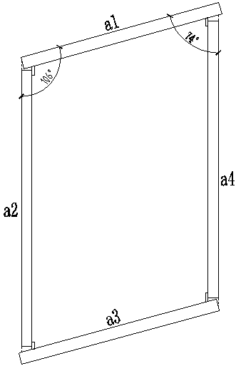
[0026] figure 1 It is a cross-sectional view of the special-shaped box according to Embodiment 1 after setting out according to the drawings. The special-shaped box is a parallelogram, and the vertex of the upper left corner is selected as the reference point. According to the protruding parts of the upper side panel and the lower side panel that exceed the left side panel and the right side panel respectively, the panels a1 and a3 are selected as the cover panels, and the panels a2 and a4 are selected as the cover panels. The web, where the cover plate and the web are both steel plates with a thickness of 30mm.

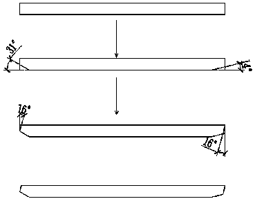
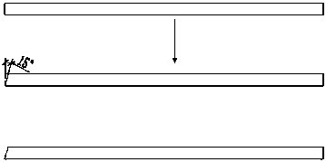
[0027] Such as figure 1 As shown, the angle formed by plate a1 and plate a2 is 106°. According to the cutting method in the prior art, the plate a1 is firstly reverse-cut 106°-90°=16°, so as to maintain a natural slope between the two, and at the same time, it is necessary to cut the groove angle of 15°, that is, reverse-cut the plate a1 by 31°, To ensure that the...

Embodiment 2

[0032] refer to Figure 8 , shows the groove cutting method of the non-parallelogram special-shaped box-shaped steel member according to the present invention. Taking the vertex of the upper left corner as the reference, the plate a5 is used as the cover plate, and the plate a6 is used as the web plate, the angle formed between them is 100°, and the plate a5 is cut back 100°-90°+30°=40°, and the blunt edge is left is 9mm, which meets the requirement of a blunt edge greater than 5mm, and the right angle of plate a6 remains unchanged. Although there is still a natural inclination of 10° between the blunt edge of plate a5 and plate a6, the natural inclination is small and basically has no effect. Therefore, it is not necessary to cut, and it can be directly wrapped when welding the wrapped surface. The angle formed between the plate a6 and the plate a7 is 89°, which is close to 90°, the natural slope between the two is 1°, the inverse cut to the plate a7 is 15°, and the tangent ...

Embodiment 3

[0034] refer to Figure 9 , shows the groove cutting method of the pentagon special-shaped box-shaped steel member according to the present invention. Taking the vertex of the upper left corner as the reference point, the angle formed by plate a9 and plate a10 is 125°, select plate a9 as the cover plate, if the cover plate a9 is cut 125°-90°+30°=65°, it cannot be satisfied as a plate The requirement of 5mm blunt edge is reserved for a9, so under the condition of reserving 5mm blunt edge for plate a9, reverse cut 125°-90°+20°=55° for plate a9, and the gap between the cover plate and the web after cutting must be satisfied. The angle between the plates a10 and a11 is also 125°, the plate a11 is selected as the cover plate, and the cut of the plate a11 is 65°-55°=10°. The method is the same as that of plate a9, anti-cut 55°, plate a10 is still tangent 10°; plate a11 and plate a12 form 90°, plate a11 is anti-cut 15°, plate a12 is tangent 15°; plate a12 and plate a113 form 110° d...


PUM


Abstract

The invention provides a special-shaped box type steel component groove fabrication method. The special-shaped box type steel component groove fabrication method is realized through the following steps that step1, lofting is performed according to a special-shaped box type section size graph; step2, an angle in the special-shaped box section is taken as the reference point to select and confirm cover plates and ventral plates; step3, under the premise that blunt edges are larger than or equal to 5 mm, the cover plates are cut separately, and the sum of groove angles of cut plate blocks being spliced together is guaranteed to be 30 degrees; step4, one-time natural bevel cutting is performed on the other ends of the cover plates, included angles among the plate blocks are compensated by cutting the ventral plates, and the sum of groove angles of the cut plate blocks being spliced together is guaranteed to be 30 degrees; step5, all the angles are judged according to the step2, the step3 and the step4, and the groove cutting angle, size and direction are measured and labelled on the plate blocks; and step6, groove cutting is performed through a semi-automatic cutting machine. By meansof adoption of the special-shaped box type steel component groove fabrication method, the cutting times of the cover plates are reduced, a cutting process is simplified, and resource waste is reduced.

Description

technical field [0001] The invention belongs to the manufacturing technology of building steel structures, and in particular relates to a method for manufacturing grooves of special-shaped box-shaped steel members. Background technique [0002] At present, when making boxes made of steel members, for ordinary rectangular boxes with cross-sectional angles of 90°, it is necessary to cut 15° grooves on the cover plate and web plate before welding to realize the cover plate and web plate. Connection. However, in special-shaped box-shaped steel members, because some included angles of the special-shaped box-shaped section are not right angles (90°), they cannot be processed in the conventional groove form. According to the conventional method, directly press the box-shaped cover plate and web plate to shovel 15 degrees each. Since the angle is not regular, the natural slope of the cover plate should be cut off (defined in this paper as the difference between the angle between th...

Claims


Application Information

Patent Timeline
Patent Type & Authority Applications(China)
IPC IPC(8): B23K31/10
CPCB23K31/10
Inventor 陈宇斌
Owner CHINA 22MCC GROUP CORP
Why Eureka
Try Eureka