Hydraulic forging device

A hydraulic and forging technology, which is used in forging/pressing/hammer devices, manufacturing tools, forging/pressing/hammering machines, etc. Improve processing quality, simple structure and convenient operation

Inactive Publication Date: 2020-09-08
孙敏
View PDF0 Cites 5 Cited by
  • Summary
  • Abstract
  • Description
  • Claims
  • Application Information

AI Technical Summary

Problems solved by technology

[0004] The purpose of the present invention is to solve the shortcomings of the existing forging method, such as uneven application of force in different directions, failure to

Method used


Image

  • Hydraulic forging device
  • Hydraulic forging device
  • Hydraulic forging device

Examples


Embodiment 1

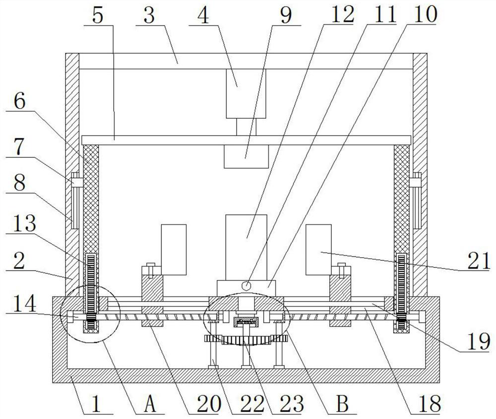
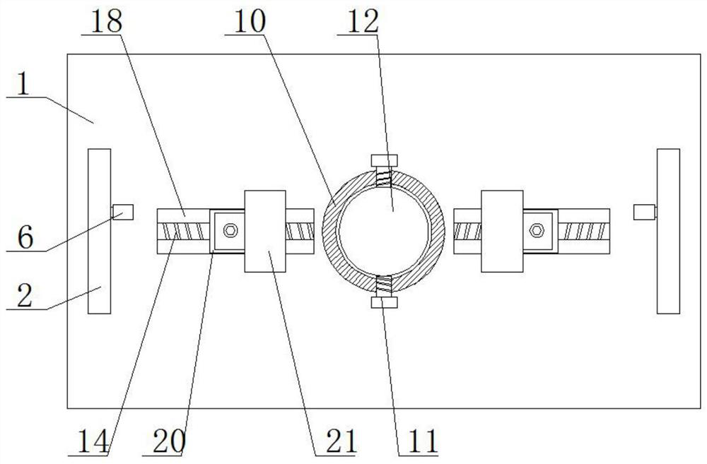
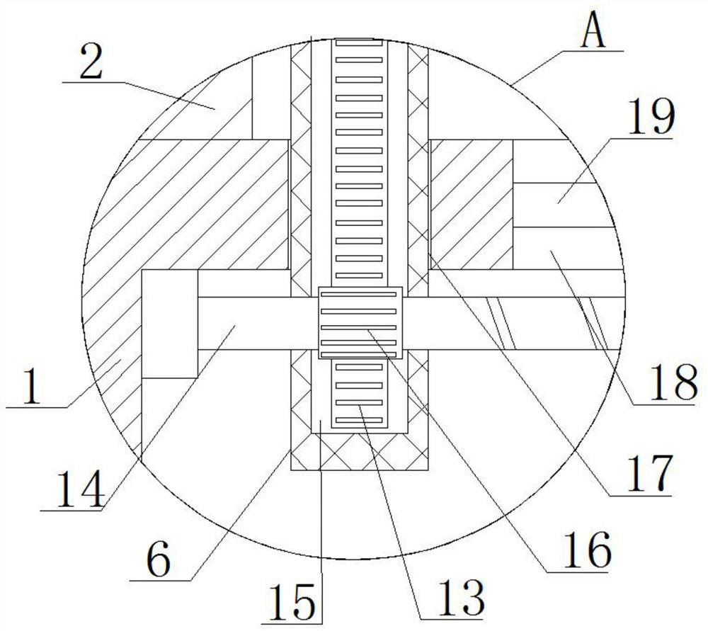
[0027] refer to Figure 1-6 , a hydraulic forging device, comprising a fixed box 1, the top of the fixed box 1 is provided with a placement seat 10, the top of the placement seat 10 is provided with a placement groove, a forging part 12 is placed in the placement groove, and the top of the fixed box 1 is fixedly installed with Two welding rods 2, the top of the two welding rods 2 is fixedly installed with the same ejector rod 3, the bottom of the ejector rod 3 is fixedly connected with a hydraulic push rod 4, and the output shaft of the hydraulic push rod 4 is fixedly connected with a connecting rod 5, The bottom of connecting rod 5 is fixedly connected with top forging head 9, and the bottom of connecting rod 5 is fixedly installed with two vertical rods 6, and two vertical rods 6 are all slidingly connected with fixed box 1, and there are two symmetrical rotations installed in fixed box 1. Threaded rod 14, two threaded rods 14 are respectively adapted to two vertical rods 6,...

Embodiment 2

[0036] refer to Figure 1-6, a hydraulic forging device, comprising a fixed box 1, the top of the fixed box 1 is provided with a placement seat 10, the top of the placement seat 10 is provided with a placement groove, and a forging part 12 is placed in the placement groove, and the top of the fixing box 1 is fixed by welding Two welding rods 2 are installed, the tops of the two welding rods 2 are fixedly installed with the same ejector rod 3 by welding, the bottom of the ejector rod 3 is fixedly connected with a hydraulic push rod 4, and the output shaft of the hydraulic push rod 4 passes The connecting rod 5 is fixedly connected with the screw, and the bottom of the connecting rod 5 is fixedly connected with the top forging head 9 through the screw, and the bottom of the connecting rod 5 is fixedly installed with two vertical rods 6 by welding, and the two vertical rods 6 slide with the fixed box 1 Connection, two threaded rods 14 are installed symmetrically through the beari...


PUM


Abstract

The invention belongs to the technical field of forging devices, and particularly relates to a hydraulic forging device. Aiming to solve the problems that an existing forging mode is uneven in force application in different directions and cannot achieve effective synchronization, so that a workpiece is unevenly deformed, and forge piece machining quality is affected, the following scheme is provided. The device comprises a fixing box, a placing seat is arranged at the top of the fixing box, a placing groove is formed in the top of the placing seat, a forge piece is placed in the placing groove, two welding rods are fixedly arranged at the top of the fixing box, the same ejector rod is fixedly arranged at the tops of the two welding rods, a hydraulic pushing rod is fixedly connected to thebottom of the ejector rod, a connecting rod is fixedly connected to an output shaft of the hydraulic pushing rod, and the bottom of the connecting rod is fixedly connected with a top forging head. According to the device, the structure is simple, the operation is convenient, multi-direction beating can be carried out, and meanwhile, the forge piece can be driven to rotate, so that the force application is uniform, and the forge piece machining quality is improved.

Description

technical field [0001] The invention relates to the technical field of forging devices, in particular to a hydraulic forging device. Background technique [0002] With the development of technology, the metal material processing field has higher and higher requirements for forging technology and product quality. It is the development trend of the forging industry to continuously promote the direction of cost reduction and high efficiency. In order to improve the efficiency and effect of forging, therefore, multi-directional Forging technology emerged at the historic moment, with the continuous increase of various types of multi-directional free forging equipment. [0003] The existing forging method applies uneven force in different directions, which cannot achieve effective synchronization, which leads to uneven deformation of the workpiece and affects the processing quality of the forging. Contents of the invention [0004] The purpose of the present invention is to sol...

Claims


Application Information

Patent Timeline
IPC IPC(8): B21J13/10B21J13/00B21J7/14
CPCB21J7/14B21J13/00B21J13/10
Inventor 孙敏
Owner 孙敏
Why Eureka
Try Eureka