A storage tank and its design calculation method

A technology for reservoirs and ponds, which is applied in construction, infrastructure engineering, protection devices, etc., can solve the problems of cumbersome active anti-floating management, increased labor costs, and high foundation requirements, and achieves protection of groundwater resources, cost savings, and engineering volume. small effect

Active Publication Date: 2022-04-15
金建工程设计有限公司
View PDF6 Cites 0 Cited by
  • Summary
  • Abstract
  • Description
  • Claims
  • Application Information

AI Technical Summary

Problems solved by technology

[0004] Aiming at the problems in the prior art of high cost of passive anti-floating design, high foundation requirements, cumbersome active anti-floating management and increased labor costs, the present invention provides a water storage tank capable of automatic drainage and anti-floating and its design calculation method

Method used


Image

  • A storage tank and its design calculation method
  • A storage tank and its design calculation method
  • A storage tank and its design calculation method

Examples


Embodiment 1

[0094] Step S02: Calculate the anti-floating stability safety factor K according to the load of the reservoir w When the requirements are met, the buried depth of the groundwater table outside the reservoir;

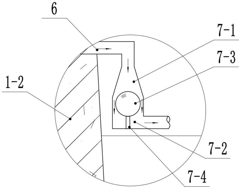
[0095] Step S03: determine the height of the seepage pipe 6 and the one-way valve 7 installed on the side wall of the reservoir;

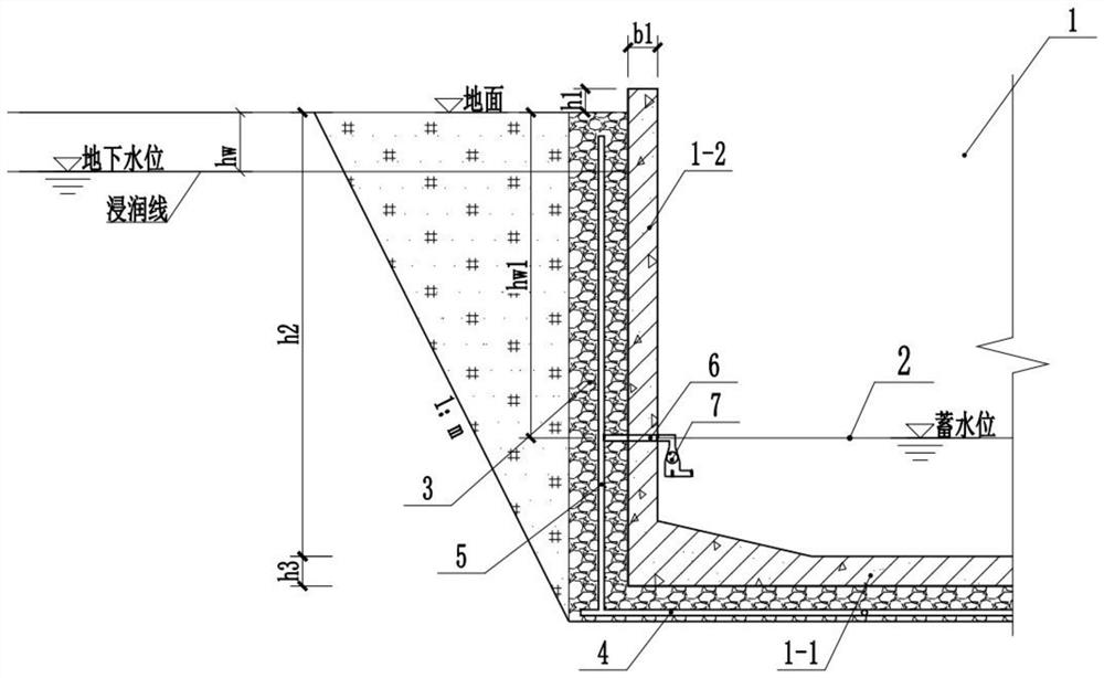
[0096] According to the automatic drainage and anti-floating method of the present invention, instead of making plain concrete counterweight, the method of lowering the groundwater level is used to calculate the minimum buried depth h of the groundwater level w1 , which is the installation height of the first layer of seepage pipe, such as figure 1 and figure 2 shown.

[0097] Buoyancy value N w,k Calculated as follows:

[0098] N w,k =A 1 ·(h 2 + h 3 -h w1 )·γ w

[0099] Calculate N w,k =7560-1890h w1

[0100] Depend on have to

[0101] get h w1 ≥2.67m.

[0102] In order to ensure that the anti-floating requirements ar...

Embodiment 2

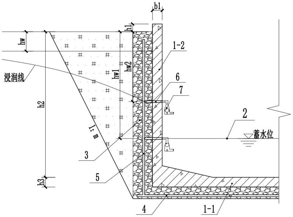
[0135] Step S06: Calculate the anti-floating stability safety factor K when the one-way valve 7 is closed w Whether the requirements are met, if yes, then execute step S07; if not, then repeat step S02 to step S06;

[0136] When the water level in the pool exceeds the installation height of the first layer of check valve 7, the first layer of check valve 7 is closed now, and the groundwater level outside the pool near the reservoir begins to rise. The water storage level 2 in the pool is considered to be consistent with the installation height of the one-way valve 7, and the groundwater level outside the pool near the reservoir is considered to be buried in the same depth as the original groundwater level (the most unfavorable case), and the anti-floating stability at this time is calculated, as image 3 shown.

[0137] At this time, by

[0138] Anti-floating stability does not meet the requirements, so it is required to install a second layer of drainage pipe.

[0139] W...

Embodiment 3

[0155] When the water level in the pool exceeds the installation height of the second layer of check valve 7, the two layers of check valve 7 are closed now, and the groundwater level outside the pool near the reservoir begins to rise. The water storage level 2 in the pool is considered to be consistent with the installation height of the second-layer one-way valve 7, and the groundwater level outside the pool near the reservoir is considered to be buried in the same depth as the original groundwater level (the most unfavorable case), and the anti-floating stability at this time is calculated. like Figure 5 shown.

[0156] At this time, by

[0157] Anti-floating stability does not meet the requirements, so a third layer of drainage pipe 6 is required.

[0158] When the water level in the pool exceeds the installation height of the second layer of check valve 7, the lower two layers of check valve 7 are all closed this moment. The water level in the pond is considered by ...


PUM


Abstract

The invention relates to a water storage tank, which comprises a water storage tank body and a seepage drainage layer. The water storage tank body includes a pool bottom and a pool side wall, and a seepage drainage layer is arranged around the pool bottom and the pool side wall. The horizontal seepage collection pipe and the vertical seepage collection pipe connected in a criss-cross pattern are arranged in the described seepage drainage layer, and the side walls of the horizontal seepage collection pipe and the vertical seepage collection pipe are provided with seepage holes; The seepage pipe communicates with the seepage discharge pipe, and the seepage discharge pipe passes through the side wall of the pool and communicates with the one-way valve in the reservoir body. The invention also includes a design calculation method for the water storage tank. In the present invention, horizontal seepage collection pipes and vertical seepage collection pipes connected in a criss-cross pattern are arranged in the seepage drainage layer to realize the automatic collection of water in the seepage drainage layer into the reservoir, thereby reducing the impact of the seepage drainage layer on the superstructure. The buoyancy of the material ensures the safety of the building; by setting the one-way valve, the groundwater in the seepage layer can only flow in one direction, so as to avoid the pollution of the groundwater.

Description

technical field [0001] The invention relates to the field of building anti-floating technology, in particular to a water storage tank and a design calculation method thereof. Background technique [0002] The buoyancy of groundwater to underground buildings follows Archimedes' principle. When the buoyancy of water is greater than the weight of the building, if no anti-floating measures are taken, the building will be damaged by floating. In view of the buoyancy exerted by groundwater on buildings, there are currently two main methods of anti-floating and passive anti-floating. Among them, the passive anti-floating is to use the bottom plate of the pool as the force-transmitting member to resist the buoyancy, and the buoyancy is transmitted to the anchor components in the foundation (such as anti-floating pile foundation, rock-soil anchor rod, etc.) and then transmitted to the rock-soil foundation, that is, The so-called anchoring method; there is also the gravity of the cou...

Claims


Application Information

Patent Timeline
Patent Type & Authority Patents(China)
IPC IPC(8): E02D31/12
CPCE02D31/12
Inventor 田祥陈欢任光伟李瑞林白娥贾晔王敬瑞张强强孙天荣马浩翔孙佳辉
Owner 金建工程设计有限公司
Why Eureka
Try Eureka