Panoramic security monitor

A monitor and security technology applied in the field of panoramic security monitors

Inactive Publication Date: 2020-09-25
GUANGZHOU LIANJIANG SOFTWARE DEV LLC
View PDF0 Cites 4 Cited by
  • Summary
  • Abstract
  • Description
  • Claims
  • Application Information

AI Technical Summary

Problems solved by technology

[0003] Based on the inventors' findings above, the existing methods mainly have the following deficiencies, such as: due to the light reflection imaging of the light-transmitting cover used in the past equipment, the reflection and clarity of the mirror surface

Method used


Image

  • Panoramic security monitor
  • Panoramic security monitor
  • Panoramic security monitor

Examples


Embodiment 1

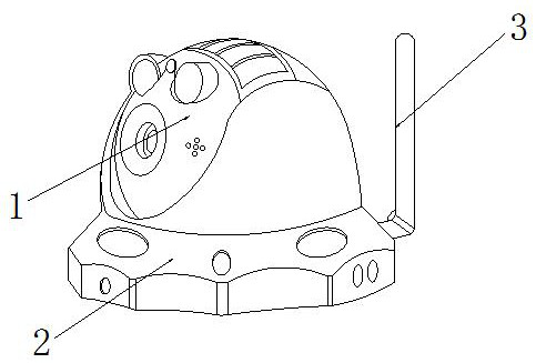
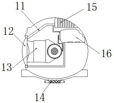
[0030] as attached figure 1 to attach Figure 5 Shown:

[0031] The present invention provides a panoramic security monitor, the structure of which includes a monitoring mechanism 1, an installation chassis 2, and a signal receiving end 3. The monitoring mechanism 1 is movable and installed directly above the installation chassis 2, and the back of the installation chassis 2 The end face is nested and engaged with the signal receiving end 3, and the signal receiving end 3 is located directly behind the monitoring mechanism 1; the monitoring mechanism 1 includes a protective baffle 11, a wide-angle lens 12, a camera 13, a rotating shaft 14, an air vent 15, Power supply 16, the protective baffle 11 is inlaid and wrapped on the outer end face of the camera 13, the wide-angle lens 12 is embedded and installed on the left side of the camera 13, and is connected with the inner end face of the monitoring mechanism 1, the camera 13 Located directly above the rotating shaft 14, the r...

Embodiment 2

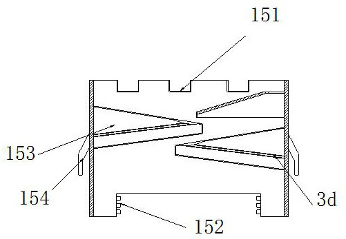
[0037] as attached Figure 5 to attach Figure 8As shown: the wide-angle lens 12 includes a connection block 121, a sealing mechanism 122, a lens crystal 123, an oleophobic layer 124, and an arc lens 125. The connection block 121 is symmetrically installed on the upper and lower sides of the lens crystal 123, and the sealing mechanism 122 is nested and wrapped on the outer lower end surface of the connecting block 121, and is connected with the lens crystal 123, the lens crystal 123 is embedded and installed on the right side of the arc lens 125, and the oleophobic layer 124 is wrapped on the arc lens 125 on the left side outer end surface, the upper and lower ends of the left side of the arc lens 125 are provided with raised blocks, the raised blocks are in the shape of a sharp cone, and when the water flow drops from top to bottom, it changes the sputtering direction , to avoid the formation of water splashes.

[0038] Wherein, the sealing mechanism 122 includes a convergi...


PUM


Abstract

The invention discloses a panoramic security monitor. The monitor structurally comprises a monitoring mechanism, a mounting chassis and a signal receiving end; the monitoring mechanism is movably clamped and mounted right above the mounting chassis; the back end surface of the mounting chassis is connected with the signal receiving end in a nesting and clamping manner; the signal receiving end ispositioned right behind the monitoring mechanism; water molecules attached to the air around equipment can flow into a ventilation opening through the air, so that the water molecules are in contact with hot air flow of a motor while slowly floating around the outer contour of a flow guide block along a flow opening, the water molecules collide and condense into water drops, the water drops flow into a flow guide pipe through the inclination angle of a flow guide conical opening and then flows to the outer side end surface of the monitoring mechanism through a water outlet, then light refraction is prevented from being influenced by a mist layer formed by water spots and water molecules, and equipment calculation errors are avoided.

Description

technical field [0001] The invention belongs to the security field, and more specifically relates to a panoramic security monitor. Background technique [0002] The panoramic security monitor is a device that obtains a wider field of view by modifying the connection end face and outer contour of the camera, and by using the calculation of the light reflection and feedback system of the arc-shaped light-transmitting cover. [0003] Based on the inventors' findings above, the existing methods mainly have the following deficiencies, such as: due to the light reflection imaging of the light-transmitting cover used in the past equipment, the reflection and clarity of the mirror surface [0004] It needs very high requirements, and the air in the south is relatively humid. When looking at the cold air with a lot of moisture [0005] When in contact with the constant temperature power supply system of the monitor, water molecules will condense on the mirror surface and ventilation...

Claims


Application Information

Patent Timeline
Patent Type & Authority Applications(China)
IPC IPC(8): H04N7/18
CPCH04N7/18
Inventor 吴海霞
Owner GUANGZHOU LIANJIANG SOFTWARE DEV LLC
Why Eureka
Try Eureka