A kind of tooth-by-tooth wear detector of front and rear cutter face of rotating tool and its detection method

A technology of rotating tools and detectors, which is applied in the direction of manufacturing tools, measuring/indicating equipment, metal processing equipment, etc., can solve problems such as low measurement efficiency, difficult protection, and high requirements for machine speed stability, so as to reduce processing costs and avoid processing The effect of quality problems

Active Publication Date: 2022-03-29
SHANGHAI WALNUT PRECISION TECH CO LTD
View PDF12 Cites 0 Cited by
  • Summary
  • Abstract
  • Description
  • Claims
  • Application Information

AI Technical Summary

Problems solved by technology

[0007] The purpose of the present invention is to provide a tooth-by-tooth wear detector and detection method for the front and rear sides of a rotary tool, so as to solve the problems of low precision, insufficient versatility and low measurement efficiency of the existing rotary tool wear measurement method. , Complicated calculation process, high requirements for machine tool speed stability, difficult protection, problems

Method used


Image

  • A kind of tooth-by-tooth wear detector of front and rear cutter face of rotating tool and its detection method
  • A kind of tooth-by-tooth wear detector of front and rear cutter face of rotating tool and its detection method
  • A kind of tooth-by-tooth wear detector of front and rear cutter face of rotating tool and its detection method

Examples


Embodiment Construction

[0046] The following will clearly and completely describe the technical solutions in the embodiments of the present invention with reference to the accompanying drawings in the embodiments of the present invention. Obviously, the described embodiments are only some, not all, embodiments of the present invention. Based on the embodiments of the present invention, all other embodiments obtained by persons of ordinary skill in the art without making creative efforts belong to the protection scope of the present invention.

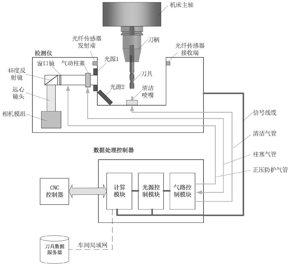
[0047] The purpose of the present invention is to provide a tooth-by-tooth wear detector for the front and rear flanks of a rotary tool and its detection method, which can realize efficient and accurate direct observation of the wear image of the front and rear flanks of each cutter tooth in a rotating state, thereby Help avoid machining quality problems caused by tool wear and reduce machining costs.

[0048] In order to make the above objects, features and a...


PUM


Abstract

The invention relates to a tooth-by-tooth wear detector and a detection method of the front and rear cutter faces of a rotary cutter. The tooth-by-tooth wear detector of the front and rear cutter faces of the rotary tool includes: a detector, a data processing controller and a tool data server; the detector and the data processing controller are connected through a signal cable; the data processing controller is also connected with the CNC control of the numerical control machine tool The detector and the tool data server are connected; the detector is equipped with a 45-degree reflector, a telecentric lens, an inclined light source and a forward light source, and the tool image sequence is obtained during the tool rotation; the data processing controller utilizes a 45-degree The mirror turns the imaging optical path by 90 degrees. Based on the gray scale response detection principle, according to the tool image sequence, the wear images of the rake face and the flank face of the rotating tool are automatically acquired and analyzed tooth by tooth directly on the machine. By adopting the invention, the efficient and accurate direct observation of the wear image of the front and back rake surfaces of each cutter tooth can be realized under the rotating state.

Description

technical field [0001] The invention relates to the field of detection of wear of a rotary tool, in particular to a tooth-by-tooth wear detector and a detection method of a front and rear cutter faces of a rotary tool. Background technique [0002] On-machine detection of rotary tools involves five mutually independent functions, namely: tool setting, multi-view detection of micro-tools, tool runout detection, tooth-by-tooth wear detection of front and rear cutter faces, and real-time monitoring of the entire machining process. , the first four functions can only be run before and after machining, and the fifth function can monitor the tool status in the whole process of CNC machining in real time. a specific attribute. This paper only studies the independent function of tooth-by-tooth wear detection on the front and back flanks. [0003] In CNC machining, the cutting of the workpiece material by the tool will cause wear on the front and rear cutter surfaces, which will af...

Claims


Application Information

Patent Timeline
Patent Type & Authority Patents(China)
IPC IPC(8): B23Q17/09
CPCB23Q17/0957
Inventor 张曦
Owner SHANGHAI WALNUT PRECISION TECH CO LTD
Why Eureka
Try Eureka