Liquid cooling heat dissipation device and heat dissipation system

A liquid-cooled heat dissipation and heat dissipation cold plate technology, which is applied in the direction of electrical components, electric solid devices, circuits, etc., can solve the problems of single and ineffective heat dissipation methods, high-efficiency heat dissipation, and low heat dissipation efficiency of heat dissipation structures, so as to improve heat dissipation efficiency and improve The degree of heat dissipation and the effect of uniform temperature

Active Publication Date: 2020-11-03
UNIV OF ELECTRONICS SCI & TECH OF CHINA
View PDF6 Cites 4 Cited by
  • Summary
  • Abstract
  • Description
  • Claims
  • Application Information

AI Technical Summary

Problems solved by technology

[0005] The present invention provides a liquid-cooled heat dissipation device and a heat dissipation system in order to solve the technical problems of low heat dissipat

Method used


Image

  • Liquid cooling heat dissipation device and heat dissipation system
  • Liquid cooling heat dissipation device and heat dissipation system
  • Liquid cooling heat dissipation device and heat dissipation system

Examples


Embodiment 1

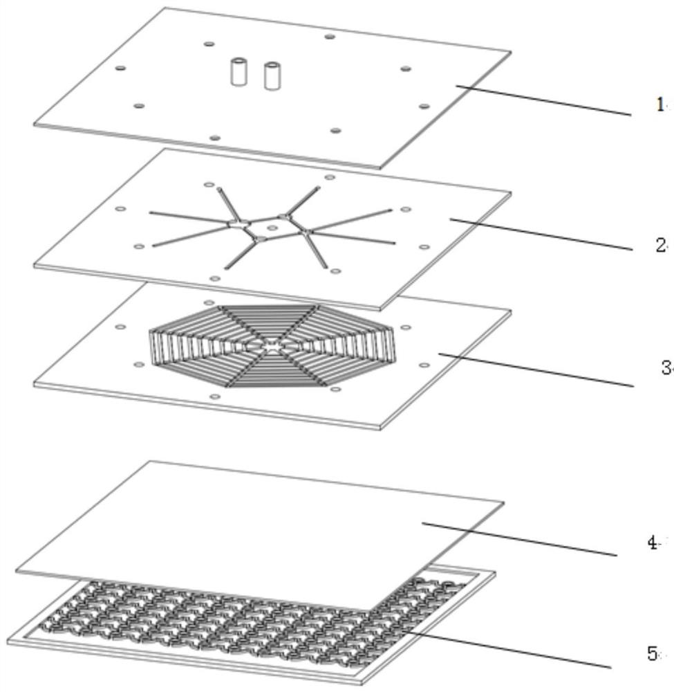
[0043] A liquid cooling device, such as figure 1 As shown, it includes a paraffin liquid cooling device and a microchannel heat dissipation cold plate, one surface of the paraffin liquid cooling device is connected to a heat source, and the other surface of the paraffin liquid cooling device is connected to the microchannel heat dissipation cold plate:

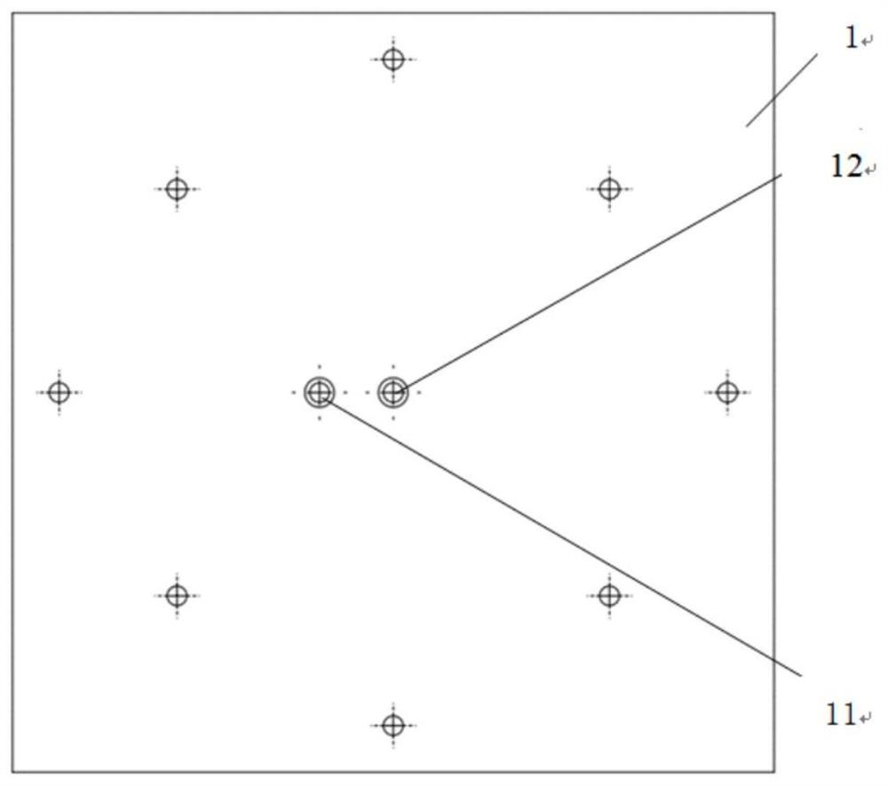
[0044] The microchannel heat dissipation cold plate includes a heat dissipation cover 1, a transitional cold plate 2 and a heat sink cold plate 3 connected in sequence; the heat dissipation cover 1 is provided with a cover liquid inlet 11 and a liquid outlet 12, and the outlet The liquid port 12 is arranged at the center of the cover plate, and the liquid inlet 11 of the cover plate can be arranged near the liquid outlet 12, such as figure 2 shown.

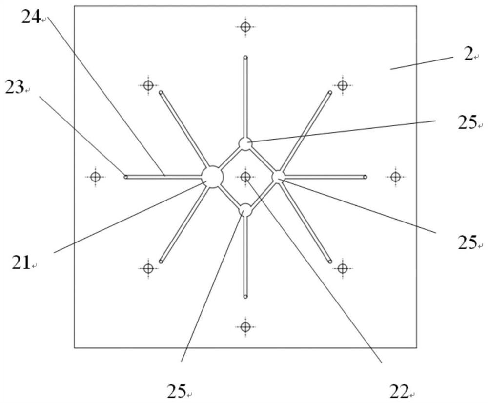
[0045] The transitional cold plate 2 is provided with a transitional liquid inlet 21, a confluence outlet 22, a number of intermediate transitional inlets 23 and a number of str...

Embodiment 2

[0052] This embodiment is based on Embodiment 1. The main flow channel 33 and the branch flow channel 34 in the heat sink cold plate 3 finally form a structure similar to a spider web. The 67.5° between the main flow channel 33 and the branch flow channel 34 is evenly distributed on both sides With numerous branch channels 34, the size of the entire heat sink cold plate 3 is 155mm*150mm*2mm, the inner diameter of the liquid inlet 31 is 4mm, the outer diameter is 6mm, the width of the main channel 33 is 2mm, and the height is 1mm. The width of the branch flow channel 34 can also be gradually increased toward the direction of the confluence port 31, the distance between the two branch flow channels 34 is 4.62 mm, the size of the innermost branch flow channel 34 is 2.49 mm, and the second layer of branch flow channels 34 is 1.39mm, the width of the third branch flow channel 34 is 1.57mm, the width of the fourth layer branch flow channel 34 is 1.75mm, and the branch flow channel 34...

Embodiment 3

[0054] In this embodiment, the performance of the microchannel heat dissipation cold plate is described.

[0055] Experiment 1 (for the same split channel width)

[0056] Experimental conditions: the micro-channel heat dissipation cold plate is made of aluminum, and the cooling liquid is clear water. The entrance condition is: the speed entrance is 0.5m / s. Outlet conditions: pressure outlet, the reference pressure adopts standard atmospheric pressure. Heating device: A heat source with a size of 120mm*67mm*2mmd is attached to the bottom of the micro-channel heat dissipation cold plate, and the heating power of the heat source is 150W.

[0057] Simulation results:

[0058] The surface temperature distribution is as Image 6 As shown, the peak temperature of the wall surface of the microchannel heat dissipation cold plate is 306.4578K, and the minimum temperature is 300K, the temperature difference is small and the temperature is relatively uniform.

[0059] The flow veloci...


PUM


Abstract

The invention discloses a liquid cooling heat dissipation device and a heat dissipation system, the liquid cooling heat dissipation device comprises a paraffin liquid cooling heat dissipation device and a micro-channel heat dissipation cold plate, one surface of the paraffin liquid cooling heat dissipation device is connected with a heat source, and the other surface of the paraffin liquid coolingheat dissipation device is connected with the micro-channel heat dissipation cold plate; the heat dissipation system comprises a liquid cooling heat dissipation device, a circulating water pump, a sensing system, a controller, a liquid storage tank and a fan, wherein the paraffin liquid cooling heat dissipation device and the micro-channel heat dissipation cold plate are combined for use; meanwhile, the heat dissipation system is adopted for intelligent control, so timely cooling can be effectively conducted according to the temperature change of a heat source, and the heat dissipation degreeof the heat dissipation system is improved.

Description

technical field [0001] The invention belongs to the field of mechanical heat dissipation, and in particular relates to a liquid cooling heat dissipation device and a heat dissipation system. Background technique [0002] In view of the increasing heat generation of current phased array antennas, a large number of T / R components form independent heating units, high heat flux density and local high temperature, greatly reducing the service life of phased array antennas. The current heat dissipation method of military high-power LEDs is almost the traditional air-cooled heat dissipation method, while for military phased array antennas, the current heat dissipation method is mainly air-cooled. There are related reports on liquid-cooled heat dissipation technology, but it is only limited to theory. And the experimental stage, there is no practical application stage yet. As the power of electronic equipment becomes higher and higher, the integration requirements become larger and ...

Claims


Application Information

Patent Timeline
IPC IPC(8): H01L23/473H01L33/64
CPCH01L23/473H01L33/648
Inventor 韦士腾徐尚龙
Owner UNIV OF ELECTRONICS SCI & TECH OF CHINA
Why Eureka
Try Eureka