Method for Monitoring Clearance of Blade Tip Tower

Active Publication Date: 2021-11-23
SHANGHAI ELECTRIC WIND POWER GRP CO LTD
View PDF1 Cites 0 Cited by
  • Summary
  • Abstract
  • Description
  • Claims
  • Application Information

AI Technical Summary

Problems solved by technology

[0003] The existing blade tip tower headroom monitoring system has at least the following problems. It will be affected by the harsh environment, cannot obtain the real headroom value, and cannot give an alarm to the situation that the blade tip tower headroom is too small

Method used


Image

  • Method for Monitoring Clearance of Blade Tip Tower
  • Method for Monitoring Clearance of Blade Tip Tower
  • Method for Monitoring Clearance of Blade Tip Tower

Examples


Embodiment Construction

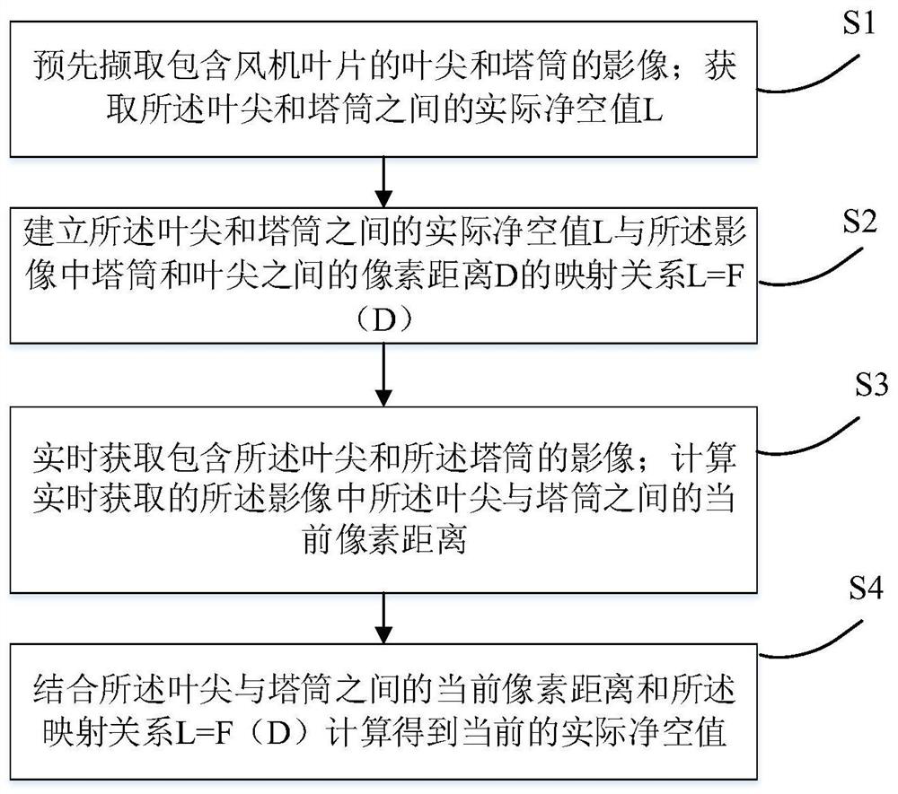
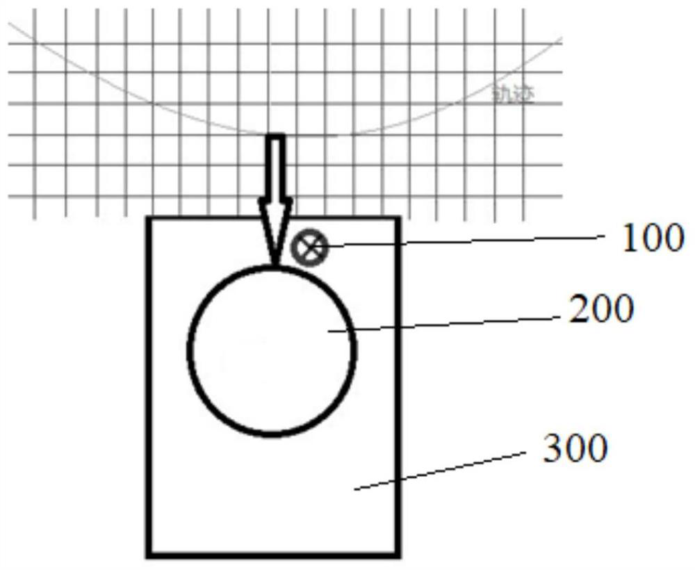
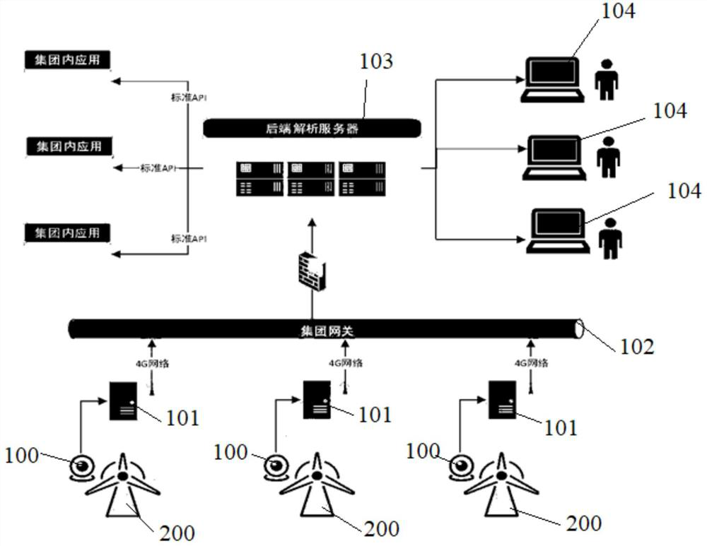
[0021] The following is attached Figure 1~3 and Specific Embodiments A blade tip tower clearance monitoring system and monitoring method proposed in the present invention will be further described in detail. The advantages and features of the present invention will become clearer from the following description. It should be noted that the drawings are in a very simplified form and all use imprecise scales, which are only used to facilitate and clearly assist the purpose of illustrating the embodiments of the present invention. In order to make the objects, features and advantages of the present invention more comprehensible, please refer to the accompanying drawings. It should be noted that the structures, proportions, sizes, etc. shown in the drawings attached to this specification are only used to match the content disclosed in the specification, for those who are familiar with this technology to understand and read, and are not used to limit the implementation of the pres...


PUM


Abstract

The invention discloses a method for monitoring the clearance of the blade tip and the tower, which includes pre-capturing the image of the blade tip and the tower including the fan blade; obtaining the actual clearance value L between the blade tip and the tower; establishing the blade tip and the tower The mapping relationship L=F(D) between the actual clearance value L between the tower and the pixel distance D between the tower and the blade tip in the image; real-time acquisition of the image containing the blade tip and the tower; Calculate the current pixel distance between the blade tip and the tower in the image acquired in real time; combine the current pixel distance between the blade tip and the tower with the mapping relationship L=F(D) to calculate the current The present invention realizes the real-time tracking and monitoring of the clearance of the tip tower tube of the wind power generator.

Description

technical field [0001] The invention relates to the technical field of wind power, in particular to a method for monitoring the clearance of a blade tip tower. Background technique [0002] The clearance of the blade tip and the tower refers to the minimum distance between the tip of the blade and the tower when the blade passes the tower when the fan generator is rotating. The blades will be deformed in the waving direction, shimmy direction and torsional direction under different wind conditions. In order to prevent the deformed blades from touching the tower, the clearance of the blade tip tower under various working conditions will be simulated at the early stage of fan design. distance to ensure the normal operation of the fan and avoid blade sweeping accidents. As the length of the blades increases, the requirements for the minimum headroom of the wind turbine become more and more stringent. [0003] The existing blade tip tower headroom monitoring system has at leas...

Claims


Application Information

Patent Timeline
Patent Type & Authority Patents(China)
IPC IPC(8): F03D17/00
CPCF03D17/00
Inventor 王蓓姜磊许王建吴姗姗
Owner SHANGHAI ELECTRIC WIND POWER GRP CO LTD
Why Eureka
Try Eureka