

Image capturing device
A camera device, camera technology, used in measuring devices, using optical devices, measuring distances, etc.
- Summary
- Abstract
- Description
- Claims
- Application Information
AI Technical Summary
Problems solved by technology
Method used
Image

Examples
Embodiment approach 1
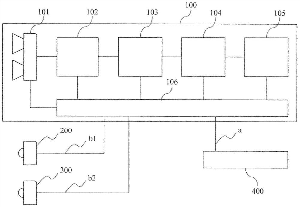
[0045] figure 1 It is a configuration diagram of the stereo camera 100 according to Embodiment 1 of the present invention. The stereo camera 100 is an imaging system that projects structured light using headlights mounted on a vehicle. The stereo camera 100 has an optical unit 101 , a signal processing unit 102 , a distance calculation unit 103 , an object recognition unit 104 , a vehicle control unit 105 , and a control unit 106 . A vehicle equipped with a stereo camera 100 has a headlight 200 , a headlight 300 , and a vehicle controller 400 . The signals a, b1, and b2 will be described later.
[0046] The stereo camera 100 starts a distance measuring operation after performing a start-up operation and a self-diagnosis when the accessory power of the vehicle on which the stereo camera is mounted is turned on. The optical unit 101 has two pairs of lenses and imaging elements. The optical unit 101 determines exposure settings such as shutter speed and gain based on informat...
Embodiment approach 2
[0080] Figure 17 It is a configuration diagram of a stereo camera 700 according to Embodiment 2 of the present invention. The stereo camera 700 projects structured light using a laser light source. The optical unit 701 to the control unit 706 are functional units similar to the optical unit 101 to the control unit 106 in the first embodiment. A vehicle equipped with a stereo camera 100 has a laser light source 707 and a vehicle controller 400 . The laser light source 707 controls the pattern, projection area, light intensity, etc. of the structured light based on the signal sent from the control unit 706 . The signals a and b will be described later.
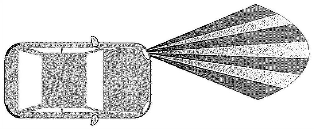
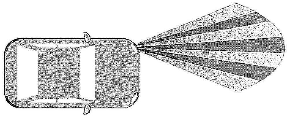
[0081] Figure 18 This is an example of a projection pattern when the laser light source 707 projects structured light. For illustration, structured light is shown with 2 straight lines extending in the direction of travel. The darker the color, the higher the illuminance, and the lighter the color, the lower the illumina...
Embodiment approach 3
[0101] Figure 27 It is a configuration diagram of the video camera 1000 according to Embodiment 3 of the present invention. In Embodiment 3, the optical unit 1001 has a pair of lenses and imaging elements. The signal processing unit 1002 to the control unit 1006 are functional units similar to those of the signal processing unit 102 to the control unit 106 in the first embodiment. Embodiment 3 differs from Embodiment 1 in that the relative position between the edge portion formed at the boundary between the low-illuminance portion and the high-illuminance portion and the optical portion 1001 is known. Other than that, it is the same as Embodiment 1. Also in this third embodiment, the distance can be measured by the same principle as that of the first embodiment.
PUM
 Abstract
Description
Claims
Application Information