Occlusion device

A sealing device and sealing part technology, which is applied in medical science, surgery, etc., can solve the problem of weak turning ability of the fixed disk, and achieve remarkable and improved effects

Active Publication Date: 2021-02-05
LIFETECH SCIENTIFIC (SHENZHEN) CO LTD
View PDF6 Cites 1 Cited by
  • Summary
  • Abstract
  • Description
  • Claims
  • Application Information

AI Technical Summary

Problems solved by technology

[0003] Based on this, it is necessary to provide an improved blocking device for the problem that the existing above-mentioned fixed plate with woven mesh structure is weak in overturning ability

Method used


Image

  • Occlusion device
  • Occlusion device
  • Occlusion device

Examples


Embodiment 1

[0031] The occlusion device proposed in Example 1 can be used to occlude the left atrial appendage, and can also be used to occlude other tissues in the body with openings, such as atrial septal defect. In the following, the closure device will be described in detail by taking the closure of the left atrial appendage as an example.

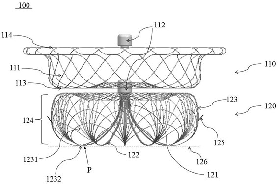
[0032] Please refer to figure 1 , the occlusion device 100 includes a sealing portion 110 and a fixing portion 120 connected to the sealing portion 110 . The sealing portion 110 and the fixing portion 120 are arranged at intervals along the axial direction of the occluding device 100 . The sealing part 110 is located at the proximal end of the occluding device 100 , and the fixing part 120 is located at the distal end of the occluding device 100 . The occlusion device 100 has a compressed state contained in the sheath for delivery in the body, and protrudes outward from the distal end of the sheath and self-expands and expands as shown in FIG. ...

Embodiment 2

[0044] The occlusion device 200 of Embodiment 2 is generally similar to the occlusion device 100 of Embodiment 1, and the same features thereof will not be repeated here. The main difference between Example 2 and Example 1 is that, as Figure 5 As shown, the proximal end of the supporting mesh 223 is closed, and the first braided wire 1231 at the proximal end of the supporting mesh 223 is spread out radially from the main end portion 121 and stretches for a certain distance toward the distal end, and then outwards toward the sealing portion 110 Turn over, then continue to extend a certain distance towards the direction of the sealing part 110, and finally, the distal end of the supporting net 223 is bent towards the inside of the fixing part 120, so as to prevent the end of the supporting net 223 from abutting against the cavity of the left atrial appendage after the fixing part 220 is deployed wear on the wall. The proximal end of the support net 223 can be closed and fixed ...

Embodiment 3

[0049] The blocking device 300 of the third embodiment is generally similar to the blocking device 100 of the first embodiment and the blocking device 200 of the second embodiment, and the same features thereof will not be repeated here. The main difference between embodiment 3 and embodiment 1, embodiment 2 is that, as Image 6 As shown, the fixing part 320 includes a main end part 121 located at its proximal end and a lead-out section 326 connected to a distal end of the main end part 121 . The lead-out section 326 is braided by the third braided wire 3261 to form a mesh tube with a hollow interior and openings at both ends. The proximal end is closed and fixed by the main end portion 121, and the distal end is fixedly connected to a plurality of flipping rods 122 respectively. The connection method can be: Welding, bonding, socketing through sleeves, etc.

[0050] The distal end of the lead-out section 326 is open, and the distal edge is fixedly connected with the support ...


PUM


Abstract

The invention relates to an occlusion device which comprises a sealing part and a fixing part connected with the sealing part, wherein the fixing part comprises a supporting net and at least one overturning rod connected with the supporting net, the supporting net is woven into a net shape through first weaving wires, each overturning rod is made into a rod shape by cutting a tubular part or is made into a rod shape by winding a plurality of second weaving wires, one end of each overturning rod extends towards the far end and then overturns outwards towards the the sealing part in the unfolding process of the fixing part, and at least one part of the supporting net forms at least one part of the side wall of the fixing part after the fixing part is unfolded. In the occlusion device, the atleast one overturning rod enables the fixing part to have higher overturning strength so that the fixing part can be overturned more easily and completely, and the situation that the left auricle isabraded or punctured due to the fact that a certain part of the fixing part abuts against the interior of a gully between pectinate muscles is avoided.

Description

technical field [0001] The invention relates to the technical field of interventional medical devices, in particular to a blocking device. Background technique [0002] In the technical field of left atrial appendage occluder, the fixed plate used for implanting into the left atrial appendage to play a role of support and fixation is currently made of braided wire with a small wire diameter to make a braided mesh, or use The tubular member is cut by means of laser cutting or the like to form a skeleton structure comprising a plurality of support rods, that is, the fixed plate is made by a pure weaving method or a pure cutting method. The support strength of the fixed disk made by cutting is higher than that of the braided mesh, but there is often a problem of stress concentration, or the problem that the support rod is easy to puncture the weak gully between adjacent comb muscles in the left atrial appendage. For the mesh structure made entirely of braided wires for the fix...

Claims


Application Information

Patent Timeline
Patent Type & Authority Applications(China)
IPC IPC(8): A61B17/00
CPCA61B17/0057A61B2017/00606A61B2017/00623
Inventor 李安宁刘建勇贾佳汤麟
Owner LIFETECH SCIENTIFIC (SHENZHEN) CO LTD
Why Eureka
Try Eureka