Connection structure of motor rotor and bearing

A technology of connecting structure and motor rotor, applied in the direction of casing/cover/support, magnetic circuit shape/style/structure, electrical components, etc. Increase the weight of the motor and other issues to achieve the effect of reducing weight, improving power density and saving costs

Inactive Publication Date: 2018-07-06
SHANGHAI DAJUN TECH
View PDF3 Cites 1 Cited by
  • Summary
  • Abstract
  • Description
  • Claims
  • Application Information

AI Technical Summary

Problems solved by technology

[0002] Usually the motor rotor includes a shaft and an iron core, such as figure 1 As shown, the iron core 2 is set on the outer ring of the rotating shaft 1 through the key 3, and the rotor iron core 2 and the stator iron core make the rotating shaft 1 generate a rotational torque through magnetic field induction. 4 and 5 are used for support. At present, the bearings 4 and 5 on the front and back of the rotating shaft 1 are arranged in an arrangement in which the outer ring of the bearing is fixed and the inner ring rotates; 2 The effective diameter area of ​​the magnetic field is mainly concentrated in the outer ring of the iron core 2, so the useless diameter area 21 in the center of the rotor iron core 2 is relatively large, resulting in waste of materials, increasing the weight of the motor, and reducing the power density of the motor

Method used


Image

  • Connection structure of motor rotor and bearing
  • Connection structure of motor rotor and bearing

Examples


Embodiment Construction

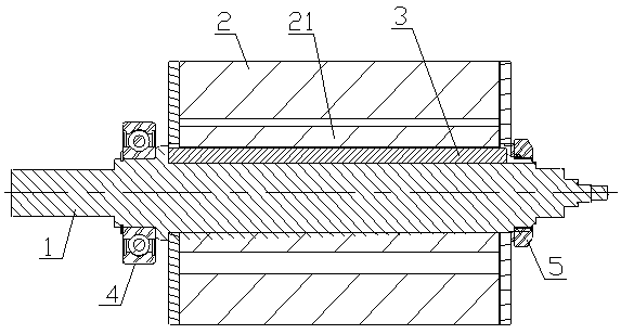
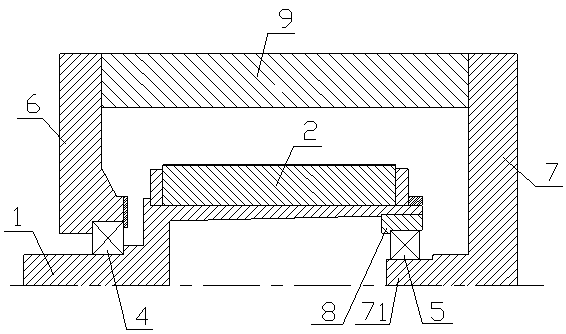
[0013] Example figure 2 As shown, the connecting structure of the motor rotor and the bearing of the present invention includes a motor shaft 1, a rotor core 2, a front bearing 4, a rear bearing 5, a front end cover 6 and a rear end cover 7, and the motor shaft 1 is a hollow with an open rear end. cup-type rotating shaft, the rotor core 2 is arranged on the outer ring of the hollow cup-type rotating shaft, the inner ring of the front bearing 4 is arranged on the outer ring of the front end of the hollow cup-type rotating shaft, and the outer ring of the front bearing 4 is arranged on the outer ring of the hollow cup-type rotating shaft In the bearing hole of the front end cover 6, the inner surface of the rear end cover 7 is provided with a cantilever shaft 71, and the inner ring of the rear bearing 5 is arranged on the cantilever shaft 71 on the inner surface of the rear end cover 7. The rear bearing The outer ring of 5 is arranged on the inner ring of the rear end of the ho...


PUM


Abstract

The present invention discloses a connection structure of a motor rotor and a bearing. The motor rotating shaft of the structure is a hollow cup-type rotating shaft with an opening at the rear end, arotor core is arranged at the outer ring of the hollow cup-type rotating shaft, a front bearing inner ring is arranged at the outer ring of the front end of the hollow cup-type rotating shaft, a frontbearing outer ring is arranged in a bearing hole of a front end cover, the inner side face of a rear end cover is provided with a cantilever shaft, the inner ring of the rear bearing is arranged at the cantilever shaft of the inner side face of the rear end cover, and the outer ring of the rear bearing is arranged at the inner ring of the rear end of the hollow cup-type rotating shaft. The structure changes the connection mode of the rotating shaft and the bearing, overcomes defect of a traditional mode of fixing of the outer ring and rotating of the inner ring, increases the cooperation diameter of the rotating shaft and the core, reduces the motor weight, saves the cost and improves the power density of the motor.

Description

technical field [0001] The invention relates to a connection structure between a motor rotor and a bearing. Background technique [0002] Usually the motor rotor includes a shaft and an iron core, such as figure 1 As shown, the iron core 2 is set on the outer ring of the rotating shaft 1 through the key 3, and the rotor iron core 2 and the stator iron core make the rotating shaft 1 generate a rotational torque through magnetic field induction. 4 and 5 are used for support. At present, the bearings 4 and 5 on the front and back of the rotating shaft 1 are arranged in an arrangement in which the outer ring of the bearing is fixed and the inner ring rotates; 2 The effective diameter area of ​​the magnetic field is mainly concentrated in the outer ring of the iron core 2, so the useless diameter area 21 in the center of the rotor iron core 2 is larger, resulting in material waste, increasing the weight of the motor, and reducing the power density of the motor. Contents of the...

Claims


Application Information

Patent Timeline
Patent Type & Authority Applications(China)
IPC IPC(8): H02K5/16H02K1/28
CPCH02K1/28H02K5/161
Inventor 李纪强周明万茂文
Owner SHANGHAI DAJUN TECH
Why Eureka
Try Eureka