Multi-line scanning distance measurement method and system

A technology of distance measurement and line scanning, which is applied in the field of distance measurement, can solve the problem of low system distance measurement accuracy, and achieve the effect of improving the distance measurement accuracy and accuracy

Pending Publication Date: 2021-02-23
ORADAR TECH CO LTD
View PDF3 Cites 5 Cited by
  • Summary
  • Abstract
  • Description
  • Claims
  • Application Information

AI Technical Summary

Problems solved by technology

[0005] The main purpose of the present invention is to propose a multi-line scanning distance measurement method and system to solve the problem of low system ranging accuracy existing in the existing multi-line scanning distance measurement technology

Method used


Image

  • Multi-line scanning distance measurement method and system
  • Multi-line scanning distance measurement method and system
  • Multi-line scanning distance measurement method and system

Examples


Embodiment Construction

[0032] In order to make the technical problems, technical solutions and beneficial effects to be solved by the embodiments of the present invention clearer, the present invention will be further described in detail below in conjunction with the accompanying drawings and embodiments. It should be understood that the specific embodiments described here are only used to explain the present invention, not to limit the present invention.

[0033] It should be noted that the terms "first" and "second" are only used for descriptive purposes, and cannot be understood as indicating or implying relative importance or implicitly indicating the quantity of indicated technical features. Thus, a feature defined as "first" or "second" may explicitly or implicitly include one or more of these features. In the description of the embodiments of the present invention, "plurality" means two or more, unless otherwise specifically defined.

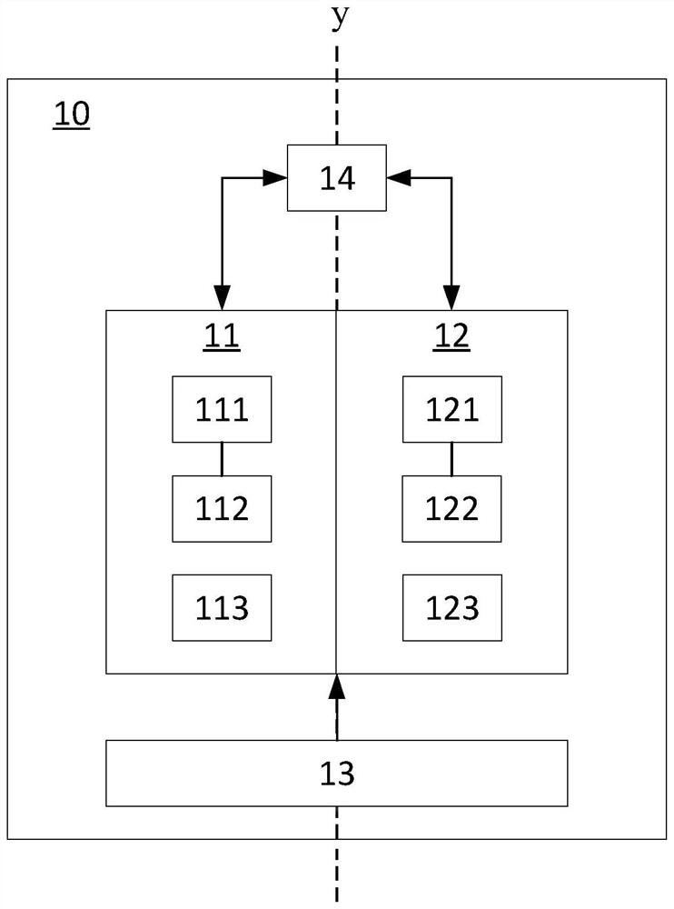
[0034] figure 1 Shown is a schematic diagram of a multi...


PUM


Abstract

The invention discloses a multi-line scanning distance measurement method and system, the system comprises an emitter, a collector and a processing circuit, the method comprises the following steps: the collector emits a pulse subset comprising n pulse beams towards a target, and adjacent pulse beams in the pulse subset have a certain time interval, wherein the time interval is set according to the divergence angle and scanning speed of the pulse beam; the collector collects photons in each pulse beam in the pulse subset reflected by the target and generates a photon signal subset; the processing circuit receives the photon signal subset and processes the photon signal subset to form a histogram, wherein the histogram comprises a detection signal subset formed by n detection signals representing a reflected pulse subset; and delay accumulation processing is performed on the detection signal subset to obtain the flight time of the pulse beam from emission to reception, and the distanceinformation of the target is solved by using the flight time.

Description

technical field [0001] The invention relates to the technical field of distance measurement, in particular to a multi-line scanning distance measurement method and system. Background technique [0002] Using the principle of time of flight (TOF, Time of Flight) can measure the distance of the target to obtain a depth image containing the depth value of the target, and the distance measurement system based on the principle of time of flight has been widely used in consumer electronics, unmanned vehicles, AR / VR and other fields. The distance measurement system based on the time-of-flight principle usually includes a transmitter and a collector. The transmitter emits a pulsed beam to irradiate the target field of view and the collector collects the reflected beam, and calculates the time required for the beam to be reflected and received to calculate the distance of the object. . [0003] At present, lidar based on the time-of-flight method is mainly divided into mechanical a...

Claims


Application Information

Patent Timeline
Patent Type & Authority Applications(China)
IPC IPC(8): G01S17/10G01S7/484G01S7/4861G01S7/4865
CPCG01S17/10G01S7/484G01S7/4861G01S7/4865
Inventor 刘超闫敏
Owner ORADAR TECH CO LTD
Why Eureka
Try Eureka