A garden waste recycling machine

A garden waste and feeder technology, which is applied in the field of waste treatment, can solve the problems of low crushing efficiency of the feeder machine, achieve the effects of improving the crushing effect, eliminating crushing dead angles, and preventing blockage of crushed materials

Active Publication Date: 2022-06-07
广东绿润环境科技有限公司
View PDF8 Cites 0 Cited by
  • Summary
  • Abstract
  • Description
  • Claims
  • Application Information

AI Technical Summary

Problems solved by technology

[0004] Based on the technical problem of low pulverization efficiency of the existing chemical material machine, the present invention proposes a garden waste chemical material machine

Method used


Image

  • A garden waste recycling machine
  • A garden waste recycling machine
  • A garden waste recycling machine

Examples


Embodiment 1

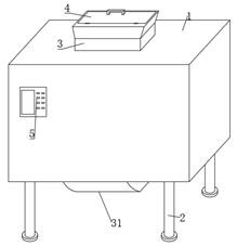
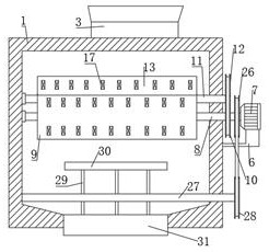
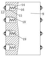
[0029] refer to Figure 1-4 , a garden waste chemical machine, including a box body 1, the bottom of the box body 1 is symmetrically fixed with a plurality of legs 2 through bolts on both sides, and the box body 1 is connected with a first straight shaft 8 and a second straight shaft 11 through hinges. , the second straight shaft 11 is disposed diagonally behind the first straight shaft 8, the first straight shaft 8 is sleeved and fixed with the first rotating roller 9, the second straight shaft 11 is sleeved and fixed with the second rotating roller 13, the first A plurality of grooves 14 distributed in an annular array are formed on the outer walls of the rotating roller 9 and the second rotating roller 13. A first sliding groove 18 is opened on the inner wall of one side of the groove 14, and a first sliding groove is slidably connected in the first sliding groove 18. Block 19, the inner side of the first slider 19 is fixed with a moving block 15 by bolts, the moving block ...

Embodiment 2

[0033] refer to Figure 1-6, a garden waste chemical machine, the box body 1 is connected with a third straight shaft 27 through a hinge rotation, the third straight shaft 27 is arranged above the discharge chute plate 31, and the third straight shaft 27 protrudes from the side close to the motor 7 A fourth pulley 28 is sleeved and fixed on the outside of the box body 1 , a third pulley 26 is sleeved and fixed on the first straight shaft 8 , and the same second belt is sleeved on the third pulley 26 and the fourth pulley 28 , the peripheral outer wall of the third straight shaft 27 is fixed with multiple groups of support rods 29 by bolts, and the top of each group of support rods 29 is fixed with the same distribution plate 30 by bolts, and the cross-sections of the distribution plate 30 and the discharge chute plate 31 are set to arc The outer wall of the distribution plate 30 is provided with a plurality of embedded grooves 32, the second spring 34 is fixed in the embedded ...


PUM


Abstract

The invention belongs to the technical field of waste treatment, in particular to a garden waste composting machine. Aiming at the problem of low pulverization efficiency of the existing composting machine, the following proposal is proposed, including a box body, which is rotatably connected with a first A straight shaft and a second straight shaft, the first straight shaft is sleeved and fixed with a first rotating roller, the second straight shaft is sleeved and fixed with a second rotating roller, the outer walls of the first rotating roller and the second rotating roller are provided with A plurality of grooves, a first chute is provided on the inner wall of one side of the groove, a first slider is slidably connected to the first chute, a moving block is fixed on the inner side of the first slider, and the moving block is arranged in the groove. A breaking knife is fixed on top of the block. In the present invention, the driving mechanism drives the first straight shaft and the second straight shaft to rotate, and then drives the first rotating roller and the second rotating roller. Under the action of centrifugal force and the first spring, the crushing knife moves back and forth in the groove, thereby The crushing knife is moved and crushed, thereby eliminating the dead angle of crushing and improving the crushing efficiency.

Description

technical field [0001] The invention relates to the technical field of waste treatment, in particular to a garden waste materializer. Background technique [0002] Plant materials such as tree and shrub trimmings, lawn trimmings, fallen leaves, branches, discarded grass and flowers in gardens and flower beds, and weeds produced by green plants in urban green spaces or suburban woodlands in nature or during maintenance. Large and medium-sized cities such as Shenzhen have begun to collect, pulverize, and compost green plant waste in a unified manner. After slicing or pulverizing, they are processed into mulch, organic substrates, and organic fertilizers for the improvement of landscaping soil. [0003] In the process of smashing the waste, the motor is generally used to drive the straight shaft to rotate, which drives the shredding knife to rotate and then pulverizes the waste added into the box. However, the existing shredding knives are generally fixed and installed. The mo...

Claims


Application Information

Patent Timeline
Patent Type & Authority Patents(China)
IPC IPC(8): B02C18/14B02C18/18B02C18/22B02C18/24B02C4/08B02C4/28B02C4/30B02C4/42B02C23/02
CPCB02C18/142B02C18/18B02C18/2225B02C18/24B02C18/0084B02C4/08B02C4/286B02C4/30B02C4/42B02C23/02B02C2201/066Y02W30/40
Inventor 来利冰
Owner 广东绿润环境科技有限公司
Why Eureka
Try Eureka