Light source glass roller
A glass and roller technology, which is applied in the field of light source glass rollers, can solve the problems of poor aesthetic effect of ripple effect and reduced light output efficiency of lamps, etc.
- Summary
- Abstract
- Description
- Claims
- Application Information
AI Technical Summary
Problems solved by technology
Method used
Image
Examples
Embodiment 1
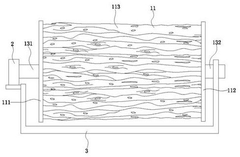
[0032] Such as image 3 , 4 , shown in 6-8; a kind of light source glass roller; comprise refraction mechanism 1, driving device 2 and support 3; Refraction mechanism 1 and driving device 2 are all installed on the support 3; Driving device 2 is connected with refraction mechanism 1; The driving device 2 drives the refracting mechanism 1 to rotate. The drive device 2 is a bidirectional drive motor. In this way, the refracting mechanism 1 can rotate forwardly or reversely.
[0033] The refraction mechanism 1 comprises a refraction device 11 ; In this embodiment, the refraction device 11 is a transparent cylindrical structure; the left refraction member 111 and the middle refraction member 113 , and the right refraction member and the middle refraction member 113 are separately arranged. In this way, the refracting device 11 is convenient to install.
[0034] More than one refraction part 12 is provided; the middle refraction member 113 is located between the left refractio...
Embodiment 2
[0043] Such as image 3 , 4 , shown in 6-8; a kind of light source glass roller; comprise refraction mechanism 1, driving device 2 and support 3; Refraction mechanism 1 and driving device 2 are all installed on the support 3; Driving device 2 is connected with refraction mechanism 1; The driving device 2 drives the refracting mechanism 1 to rotate. The drive device 2 is a bidirectional drive motor. In this way, the refracting mechanism 1 can rotate forwardly or reversely.
[0044] The refraction mechanism 1 includes a refraction device 11 and a color part (not shown in the figure); In this embodiment, the refraction device 11 is a transparent cylindrical structure; the left refraction member 111 and the middle refraction member 113 , and the right refraction member and the middle refraction member 113 are separately arranged. In this way, the refracting device 11 is convenient to install.
[0045] More than one refraction part 12 is provided; the middle refraction member ...
Embodiment 3
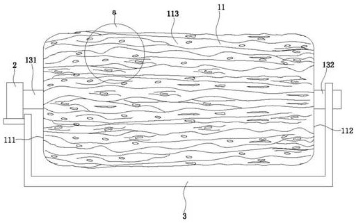
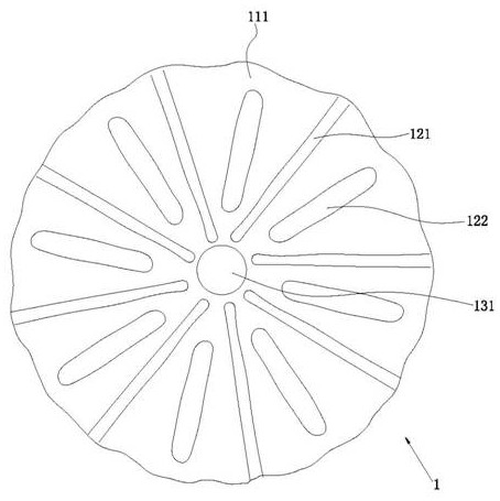
[0055] Such as figure 1 , 2 , 5, 7-8 shown; a light source glass roller; including refraction mechanism 1, driving device 2 and support 3; refraction mechanism 1 and driving device 2 are all installed on the support 3; driving device 2 and refraction mechanism 1 Connection; the driving device 2 drives the refraction mechanism 1 to rotate. The drive device 2 is a bidirectional drive motor. In this way, the refracting mechanism 1 can rotate forwardly or reversely.
[0056] The refraction mechanism 1 comprises a refraction device 11 ; In this embodiment, the left refraction element 111 and the middle refraction element 113 , and the right refraction element and the middle refraction element 113 are integrated. The sealing effect of the refraction device 11 is good.
[0057] More than one refraction part 12 is provided; the middle refraction member 113 is located between the left refraction member 111 and the right refraction member 112; the left refraction member 111 and the...
PUM
 Abstract
Description
Claims
Application Information
 - R&D
- Intellectual Property
- Life Sciences
- Materials
- Tech Scout
- Unparalleled Data Quality
- Higher Quality Content
- 60% Fewer Hallucinations
Browse by: Latest US Patents, China's latest patents, Technical Efficacy Thesaurus, Application Domain, Technology Topic, Popular Technical Reports.
© 2025 PatSnap. All rights reserved.Legal|Privacy policy|Modern Slavery Act Transparency Statement|Sitemap|About US| Contact US: help@patsnap.com


