
A heat exchanger temperature control device

A temperature control device and heat exchanger technology, applied in heat exchange equipment, lighting and heating equipment, etc., can solve the problems of increasing the water flow passing area, inaccurate manual temperature control time, and decreasing product yield, etc. area, the effect of solving the decline in product yield

Active Publication Date: 2022-07-01
RAINBOW (HEFEI) LIQUID CRYSTAL GLASS CO LTD
View PDF6 Cites 0 Cited by
  • Summary
  • Abstract
  • Description
  • Claims
  • Application Information

AI Technical Summary

Problems solved by technology

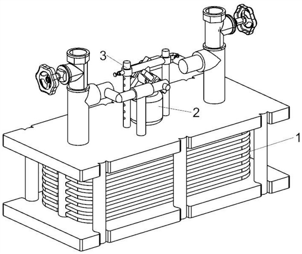
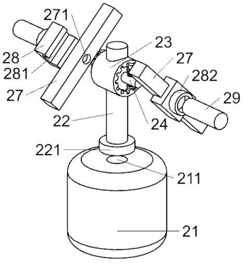
[0003] The purpose of the present invention is to overcome the above problems existing in the prior art, and provide a heat exchanger temperature control device. By providing a power component, when the temperature in the heat exchanger rises, the air pressure in the evaporation chamber rises to drive the power rod to move upward. The power rod drives the piston rod to move through the transmission to increase the water flow area, which solves the problem that the traditional manual temperature control time is inaccurate and may lead to a decline in product yield

Method used


Image

  • A heat exchanger temperature control device
  • A heat exchanger temperature control device
  • A heat exchanger temperature control device

Examples


Embodiment Construction

[0021] The technical solutions in the embodiments of the present invention will be clearly and completely described below with reference to the accompanying drawings in the embodiments of the present invention. Obviously, the described embodiments are only a part of the embodiments of the present invention, but not all of the embodiments. Based on the embodiments of the present invention, all other embodiments obtained by those of ordinary skill in the art without creative efforts shall fall within the protection scope of the present invention.

[0022] In the description of the present invention, it is to be understood that the terms "opening", "upper", "lower", "thickness", "top", "middle", "length", "inside", "around", etc. Indicates the orientation or positional relationship, only for the convenience of describing the present invention and simplifying the description, rather than indicating or implying that the components or elements referred to must have a specific orienta...


PUM


Abstract

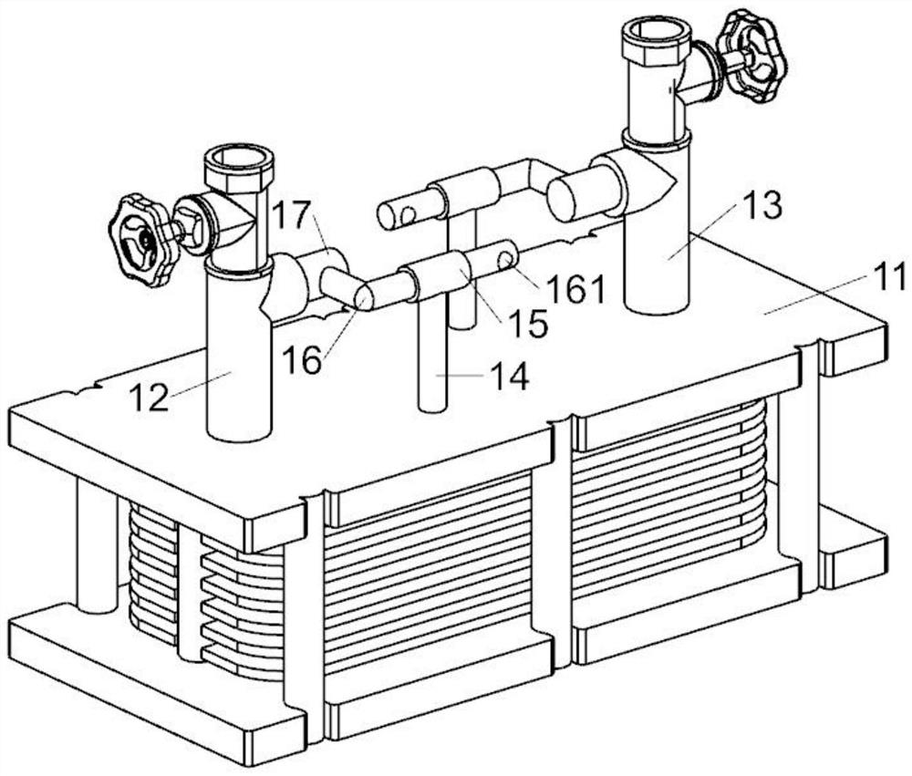
The invention discloses a heat exchanger temperature control device, which comprises a heat exchanger assembly, a power assembly is installed at the top center of the heat exchanger assembly, a guide limit assembly is installed at the top of the power assembly, and the heat exchanger assembly includes a heat exchange The top of the heat exchanger body is fixedly installed with a water inlet, the top of the heat exchanger assembly is located on one side of the water inlet, and a water outlet is fixedly installed. A vertical rod is fixedly connected to the top of the main body of the device, and a horizontally arranged guide cylinder is fixedly connected to the top of the vertical rod. The invention is provided with a power component, when the temperature in the heat exchanger rises, the air pressure in the evaporation chamber rises to drive the power rod to move upward, and the power rod drives the piston rod to move through the transmission to increase the water flow passing area, so as to solve the inaccuracy of the traditional manual temperature control time. A problem that may lead to a decrease in product yield.

Description

technical field [0001] The invention belongs to the field of heat exchanger equipment, in particular to a heat exchanger temperature control device. Background technique [0002] The temperature requirements are very high in the production process of liquid crystal glass. Too high or too low temperature of the glass liquid will reduce the yield of glass production. By adjusting the temperature of the circulating cooling water or the cooling liquid, the temperature of the muffle furnace can be accurately adjusted. At the supply end of circulating cooling water or cooling liquid, heat exchangers are often used to control the temperature of cooling water or cooling liquid. At present, the water flow rate is adjusted by adjusting the frequency of the water pump or manually adjusting the valve opening, so as to adjust the effect of the cooling water temperature. Not only the regulation reaction time lags, the regulation time is long, but also the water temperature fluctuates gre...

Claims


Application Information

Patent Timeline
Patent Type & Authority Patents(China)
IPC IPC(8): F28F27/00
CPCF28F27/00
Inventor 陈伟伟
Owner RAINBOW (HEFEI) LIQUID CRYSTAL GLASS CO LTD
Learn More