High-strength stamping die for steel

A stamping die, high-strength steel technology, applied in forming tools, manufacturing tools, metal processing equipment and other directions, can solve the problems of scratched die surface, small error range, stamping die offset of stamping parts, etc., to improve work efficiency, The effect of saving the time of manual demolding

Inactive Publication Date: 2021-03-09
无锡质诚胜精密机械科技有限公司
View PDF1 Cites 0 Cited by
  • Summary
  • Abstract
  • Description
  • Claims
  • Application Information

AI Technical Summary

Problems solved by technology

[0004]However, when the above-mentioned technical solutions are actually used, there are still many shortcomings;
[0005] 1. Since the stamping abrasive tool is not equipped with a fixing device, in actual use, when the stamping machine moves to drive the movable mold to press down, the stamping machine will vibrate to a certain extent due to the operation of the stamping machine, resulting in stamping parts in the Offset occurs on the stamping die. For some abrasive tools that require precise stamping, the error range is small. A little bit of offset will cause damage to the entire stamping part, resulting in low yield and waste of cost;
[0006] 2. Since the stamping abrasive tool is not equipped with an automatic demoulding device, it generally needs to be taken out manually after the stamping is completed. In actual use, it is often encountered that the stamping part is stuck in the mold and it is difficult to take it out. It needs to be lifted out manually. It is easy to scratch the surface of the mold during forced demoulding, which will damage the mold and greatly reduce the service life

Method used


Image

  • High-strength stamping die for steel
  • High-strength stamping die for steel
  • High-strength stamping die for steel

Examples


Embodiment Construction

[0026] The following will clearly and completely describe the technical solutions in the embodiments of the present invention with reference to the accompanying drawings in the embodiments of the present invention. Obviously, the described embodiments are only some, not all, embodiments of the present invention. Based on the embodiments of the present invention, all other embodiments obtained by persons of ordinary skill in the art without making creative efforts belong to the protection scope of the present invention.

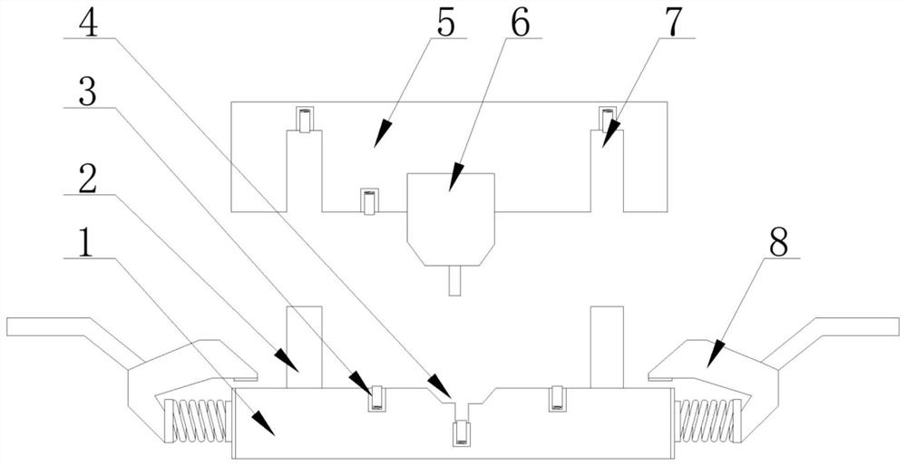
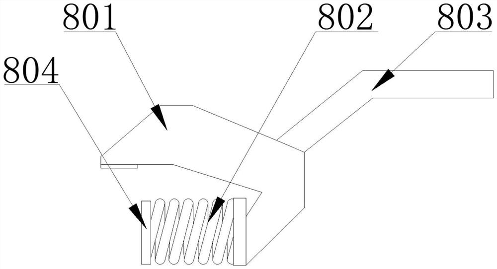
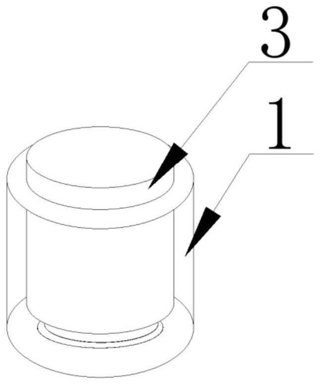
[0027] as attached Figure 1-4 A high-strength steel stamping die shown includes a fixed die 1 and a movable die 5 for stamping. The surface of the fixed die 1 is fixedly equipped with a first punch 2, and the center of the fixed die 1 is provided with a second clamping groove 4. The first punch 2 is located on both sides of the second card slot 4, the two ends of the fixed die 1 are slidingly installed with elastic clamps 8, and the two ends of the bottom sur...


PUM


Abstract

The invention discloses a high-strength stamping die for steel, in particular to the field of manufacturing of mechanical equipment. The high-strength stamping die comprises a fixed die and a moving die, wherein the fixed die and the moving die are used for stamping; a first stamping head is mounted on the surface of the fixed die; a second clamping slot is formed in the center of the fixed die; elastic pressing clips are mounted at the two ends of the fixed die in a sliding manner; first clamping slots are formed in the two ends of the bottom face of the moving die and are matched with the first stamping head; a second stamping head is fixedly mounted on a position where the bottom face of the moving die corresponds to the second clamping slot; a plurality of round holes are formed in theopposite sides of the fixed die and the moving die; and ejector pins are movably mounted in the round holes. According to the high-strength stamping die disclosed by the invention, by using the elastic pressing clips, a stamping piece can be effectively and firmly fixed to the fixed die in a descending process of the moving die, displacement of workpieces caused by vibration due to operation of machines is prevented, and the stamping piece withdraws from the surfaces of the workpieces slowly through pressure of the moving die when the moving die approaches the stamping piece, and manual operation is not required, and the problem that the yield rate caused by displacement of the stamping piece is reduced is solved.

Description

technical field [0001] The invention relates to the technical field of mechanical equipment manufacturing, and more specifically, the invention is a high-strength steel stamping die. Background technique [0002] Now the machining industry uses stamping dies, which are generally suitable for single blanking or single punching of channel steel. The blanking and punching cannot be completed at the same time. The main reason is that the volume of the I-beam is large, and the blanking and punching are made by It is completed by completely different processes, for example: the I-beam is completed by two completely different processes after blanking first and then punching, which wastes a lot of time, low work efficiency, and high labor intensity. [0003] In order to solve the above problems, a high-strength steel stamping die is disclosed in the patent application publication number CN105344835A. Figure 5 , on the basis of the existing stamping dies, the invention transforms th...

Claims


Application Information

Patent Timeline
Patent Type & Authority Applications(China)
IPC IPC(8): B21D37/10B21D37/12B21D45/02B21D37/01B21D43/00
CPCB21D37/01B21D37/10B21D37/12B21D43/003B21D45/02
Inventor 王小培
Owner 无锡质诚胜精密机械科技有限公司
Why Eureka
Try Eureka