Sludge drying and incinerating treatment process

A sludge drying and treatment method technology, applied in the direction of oxidation treatment of sludge, by-product vaporization, etc., can solve the problems of multiple harmful substances, polluting the environment, complex processes, etc., and achieve good safety, high heat utilization rate, and system structure simple effect

A sludge drying and treatment method technology, applied in the direction of oxidation treatment of sludge, by-product vaporization, etc., can solve the problems of multiple harmful substances, polluting the environment, complex processes, etc., and achieve good safety, high heat utilization rate, and system structure simple effect

CN1931753AInactive Publication Date: 2007-03-21BEIJING CHINA SCI GENERAL ENERGY & ENVIRONMENT CO LTD

Image

  • Sludge drying and incinerating treatment process
  • Sludge drying and incinerating treatment process
  • Sludge drying and incinerating treatment process

Examples


Embodiment 1

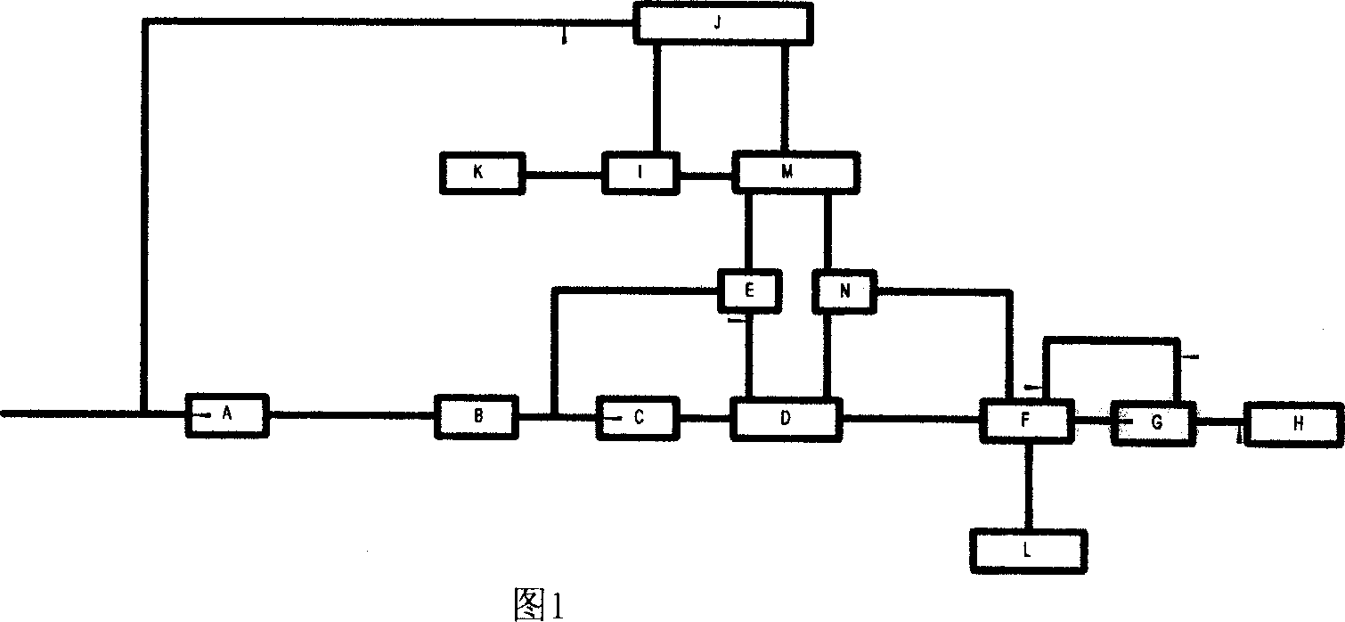
[0050] Fig. 1 is a schematic diagram of the process of the present invention. The sludge with a water content of about 95% from the sewage treatment plant and the sludge slurry sedimentation tank is first heated to 50°C, and then sent to the mechanical dehydration device A for preliminary mechanical dehydration to reduce the water content to 80% to 65%. After preliminary dehydration, the sludge is sent to the mechanical granulation device B for mechanical extrusion granulation to form columnar particles with a diameter and height of about 1-3 cm or spherical particles with a diameter of 1-3 cm. The granulated sludge is mixed with the dried sludge fine powder separated by the gas-solid separator E located at the outlet of the fluidized bed sludge drying device D, and sent to the drum mixer C for mixing and stirring to make the sludge dry The sludge fine powder adheres to the surface of wet sludge particles. The sludge particles coming out of the drum agitator C then enter the...

Embodiment 2

[0055] Wet sludge temperature (step 1)

Embodiment 3

[0057] Wet sludge temperature (step 1)


PUM

PropertyMeasurementUnit
diameteraaaaaaaaaa
heating valueaaaaaaaaaa
heightaaaaaaaaaa

Abstract

The present invention relates to environmental protection engineering technology, and is especially sludge drying and incinerating treatment process. The present invention has effective utilization of heat energy, no exhaust of harmful gas and bad smell, no exhaust of dangerous clinker, simple structure and high burning efficiency of the sludge incinerating system, no need of auxiliary fuel and other advantages.

Description

technical field [0001] The invention relates to the field of environmental protection engineering, in particular to a sludge drying and incineration treatment method. Background technique [0002] With the development of my country's social economy and the continuous expansion of urban population, the discharge of industrial wastewater and domestic sewage is increasing, and the output of sludge, a by-product of urban sewage treatment, is also increasing rapidly. Sludge is a kind of flocculent mud particles with high water content produced in the process of sewage treatment. It is actually an aggregate formed by suspended solids in sewage, microorganisms, organic matter adsorbed by microorganisms, and products of microbial metabolic activities. Sludge is often rich in nutrients such as nitrogen and phosphorus. However, untreated sludge also contains heavy metals, pathogenic bacteria, parasites, and some refractory organic poisons. If it is not handled properly! After dischar...

Claims


Application Information

Patent Timeline
21 Mar 2007
Publication
CN1931753A
IPC
C02F11/06
CPC
Y02W10/40
Inventors
蒋宏利; 姜鸿安