

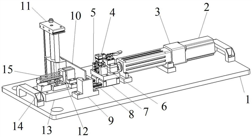
A gas valve automatic intubation device
An air valve and intubation technology, which is applied in the field of air valve automatic intubation devices, can solve the problems of low work efficiency, restricted production efficiency, incompetence of operators, etc., and achieves the effects of improving efficiency and solving the high labor intensity of installation.
- Summary
- Abstract
- Description
- Claims
- Application Information
AI Technical Summary
Problems solved by technology
Method used
Image

Examples
Embodiment Construction
[0023] The following will clearly and completely describe the technical solutions in the embodiments of the present invention with reference to the accompanying drawings in the embodiments of the present invention. Obviously, the described embodiments are only some, not all, embodiments of the present invention. Based on the embodiments of the present invention, all other embodiments obtained by persons of ordinary skill in the art without making creative efforts belong to the protection scope of the present invention.
[0024] The purpose of the present invention is to provide an air valve automatic intubation device to solve the above-mentioned problems in the prior art and improve the efficiency of air valve intubation.
[0025] In order to make the above objects, features and advantages of the present invention more comprehensible, the present invention will be further described in detail below in conjunction with the accompanying drawings and specific embodiments.
[0026...
PUM
 Abstract
Description
Claims
Application Information