Test and calculation method for measuring equivalent plastic strain forming limit diagram

A technology of equivalent plastic strain and forming limit diagram, applied in the direction of applying stable tension/pressure to test material strength, measuring device, strength characteristics, etc., can solve the problem of not covering the strain path in the shear area, EPS-FLD cannot be input, Impact and other issues

Pending Publication Date: 2021-06-15
肖锋
View PDF0 Cites 1 Cited by
  • Summary
  • Abstract
  • Description
  • Claims
  • Application Information

AI Technical Summary

Problems solved by technology

At the same time, the traditional V-FLC needs to be obtained through complex tests, and the test results will be affected by many factors, such as test tools, sample material thickness, n value, etc.
[0034] Second, for the prediction results of uniaxial tension or near uniaxial tension strain state region, V-FLD does not contain shear edge information, which is too biased towards safety judgment, that is, it cannot be used to predict edge cracking; for biaxial tension or For the prediction results close to the biaxial tensile strain state region, V-FLD is also biased towards safety judgment, that is, it cannot predict the local cracking of the biaxial tension state; for the prediction results of the plane strain or near the plane strain state region, V-FLD tends to be conservative , that is, it is predicted that there is a risk of cracking but it will not actually crack; for the shear strain state area, V-FLD does not contain shear information and does not cover this area. Therefore, no judgment can be made based on V-FLD
[0035] Third, for the edge cracking prediction of advanced high strength steel (AHSS), "patent application 2020106180963", the EPS-FLD modified based on the hole expansion rate has brought obstacles to the engineering application of this application. On the one hand, the modified EPS needs to be - The secondary development of FLD is integrated into the forming analysis software; on the other hand, the node separation of the unit needs to be considered, which will involve the modification of the kernel program of the forming analysis software. Therefore, it is unrealistic to realize the engineering application of this application in the short term of
[0036] Fourth, regarding the value range of the plastic strain ratio r, there are only two cases for the value range of r in "Patent Application 2020106180963": first, the value range of r in the main claim is [-∞,+∞], In the existing commercial forming software, the EPS-FLD of this value range cannot be input, so it cannot be practically applied in engineering at present; the second is that the value range of r from the claim is [-0.5,1], and Existing V-FLD consistent, does not cover the strain path in the shear region, therefore, for shear deformation, cannot be predicted by the EPS-FLD from the right

Method used


Image

  • Test and calculation method for measuring equivalent plastic strain forming limit diagram
  • Test and calculation method for measuring equivalent plastic strain forming limit diagram
  • Test and calculation method for measuring equivalent plastic strain forming limit diagram

Examples


Embodiment 1

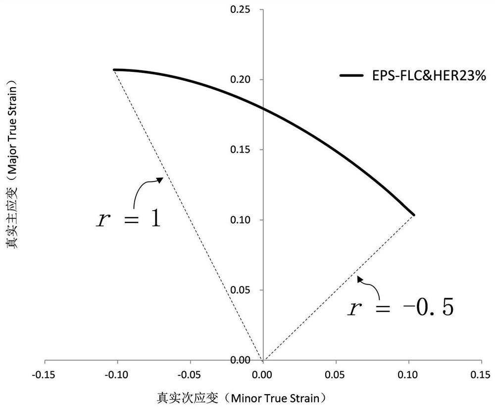
[0102] In this embodiment, the test and calculation method for determining the equivalent plastic strain forming limit diagram of the present invention is described in detail with the material DP780 / 1.4mm, including the following steps:

[0103] Step 1. According to the test method specified in the material hole expansion test standard ISO / TS 16630 or GB / T 24524-2009, the hole expansion rate λ=23% of the material DP780 is measured;

[0104] Step 2. Calculate the true fracture strain with edge damage The true fracture strain with edge damage is Calculate according to the formula:

[0105]

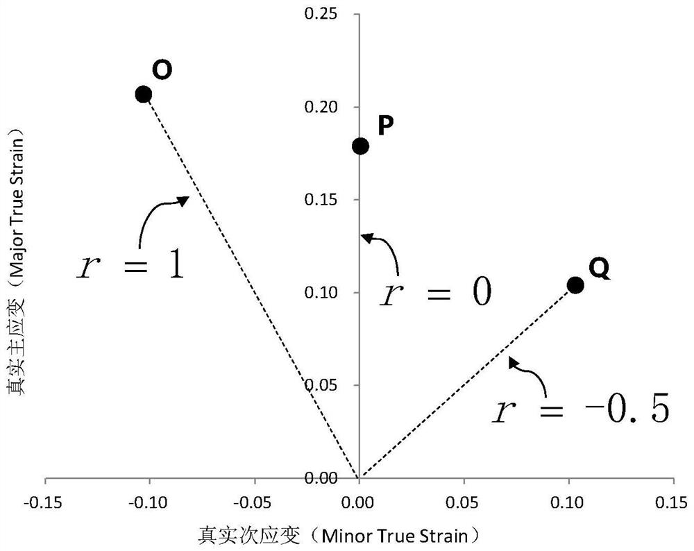
[0106] Step 3. Calculate the real principal strain ε under different simple strain paths according to the following two formulas: major and true secondary strain ε min or :

[0107]

[0108]

[0109] Among them, r is the plastic strain ratio, which is used to characterize the simple strain path, and its value range is [-0.5,1], then the corresponding ε min or The value range ...

Embodiment 2

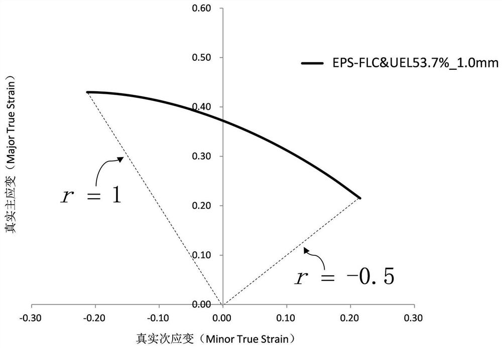
[0126] In this embodiment, the test and calculation method for determining the equivalent plastic strain forming limit diagram of the present invention is described in detail with the material DP780 / 1.4mm, including the following steps:

[0127] Step 1. Determine the uniform elongation of the material The uniform elongation It means: in the uniaxial tensile test, in the fracture center area of ​​the sample, the length, width and height taken are l 10 ·w 10 The maximum engineering strain of a 1.4mm finite body A that is always under uniform necking deformation is calculated by the following formula:

[0128]

[0129] Among them, the initial gauge length l 10 =10mm, initial width w r =10mm, the subscript r=10 indicates the size of the initial gauge length and initial width, l UEL It means that the measured deformation length of finite body A at the end of uniform necking is 12.71 mm.

[0130] Step 2. Calculate the true uniform strain The true uniform strain Calcul...


PUM


Abstract

The invention discloses a test and calculation method for measuring an equivalent plastic strain forming limit diagram. The test and calculation method comprises the following steps: measuring the hole expansion rate or uniform elongation rate of a material; calculating real fracture strain or real uniform strain with edge damage; calculating real main strain and real secondary strain under different simple strain paths; and drawing an equivalent plastic strain forming limit curve. According to the method, various defects in the prior art are overcome, a feasible engineering solution is provided for edge cracking prediction of advanced high-strength steel, the material testing cost is reduced, and the labor cost and the equipment investment are saved. The measured equivalent plastic strain forming limit curve can be directly input into existing forming simulation business software, the accuracy of a prediction result can be visually verified, engineering application is accelerated, and therefore the method has important theoretical and engineering practical significance.

Description

technical field [0001] The invention relates to a test and calculation method for determining equivalent plastic strain forming limit diagrams, in particular to a test and calculation method for equivalent plastic strain, bilinear and single linear forming limit diagrams for uniform forming or with edge damage. Background technique [0002] Forming Limit Diagram (FLD for short) was jointly proposed by Keeler (SAE technical paper 650535) and Goodwin (SAE technical paper 680093) in the 1960s. Keeler proposed that the right half area is used for the analysis of the simple strain state area of ​​the double tension deformation of the sheet metal, and Goodwin extended the left half area for the analysis of the simple strain state area of ​​the sheet metal tension-compression deformation on the basis of Keeler. [0003] FLD describes the limit combination of true principal strain (ordinate) and true secondary strain (abscissa) near the local necking state under different simple str...

Claims


Application Information

Patent Timeline
IPC IPC(8): G01N3/08G01N3/02
CPCG01N3/08G01N3/02
Inventor 肖锋
Owner 肖锋
Why Eureka
Try Eureka