Friction stir welding tool and friction stir welding method

A technology of friction stir and welding methods, which is applied in the field of friction stir welding tools and friction stir welding, which can solve the problems of long length and impact on the durability of friction stir welding tools, and achieve buckling suppression, reduced operating costs, and improved durability Effect

Active Publication Date: 2021-06-22
KAWASAKI HEAVY IND LTD
View PDF13 Cites 0 Cited by
  • Summary
  • Abstract
  • Description
  • Claims
  • Application Information

AI Technical Summary

Problems solved by technology

[0006] In addition, when the thickness of the heavy leather part is large, the length between the upper and lower gaps may be longer
In this case, a larger rotational moment acts on the side of the stirring shaft where the friction stir welding tool is attached to the main body, thereby buckling the stirring shaft and possibly affecting the friction stir welding tool. Durability

Method used


Image

  • Friction stir welding tool and friction stir welding method
  • Friction stir welding tool and friction stir welding method
  • Friction stir welding tool and friction stir welding method

Examples


no. 1 Embodiment approach

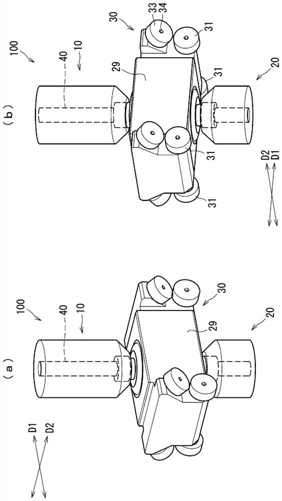
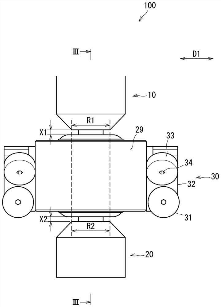
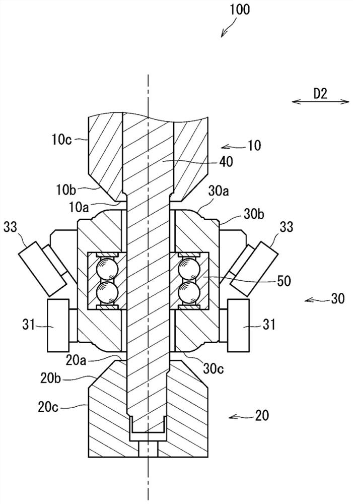
[0025] Hereinafter, a tool for friction stir welding according to a first embodiment of the present invention will be described with reference to the drawings. exist figure 1 (a) shows a perspective view of the friction stir welding tool 100 according to the first embodiment viewed obliquely from above. figure 1 (b) shows the perspective view which looked at the tool 100 for friction stir welding which concerns on 1st Embodiment obliquely from below. exist figure 2 A side view of the tool 100 for friction stir welding is shown in . exist image 3 A cross-sectional view of the tool 100 for friction stir welding is shown in . image 3 is along figure 2 Sectional view of line III-III.

[0026] like Figure 1 ~ Figure 3 As shown, the friction stir welding tool 100 of this embodiment includes an upper shoulder (first shoulder portion) 10, a lower shoulder (second shoulder portion) 20, an intermediate shoulder (third shoulder portion) 30, and Agitator shaft 40. The middle...

no. 2 Embodiment approach

[0095] Next, a friction stir welding tool 100b according to a second embodiment of the present invention will be described. In addition, the description of the part which has the same structure as that of the said 1st Embodiment is abbreviate|omitted, and only a different part is demonstrated.

[0096] In the second embodiment, the opposing portion (first opposing portion) 35a facing the upper shoulder 10 via the upper slit x1 of the intermediate shoulder 30 and the lower platform via the lower slit x2 are configured. The opposing parts (second opposing parts) 35b facing the shoulders 20 can move relative to each other in the axial direction of the stirring shaft 40, and elastic bodies are arranged between the opposing parts. The implementation is different.

[0097] exist Figure 8 A side view of the tool 100b for friction stir welding in the second embodiment is shown in . exist Figure 8 (a) shows that the distance between the facing portion 35a facing the upper shoulde...

no. 3 Embodiment approach

[0104] Next, a friction stir welding tool 100c according to a third embodiment of the present invention will be described. In addition, the description of the part which has the same structure as the said 1st Embodiment and 2nd Embodiment is abbreviate|omitted, and only a different part is demonstrated.

[0105] In the third embodiment, the positions of the beam members w3 included in the workpieces W to be subjected to friction stir welding are different from those in the first and second embodiments. Along with this, the shape when viewed from the front of the intermediate shoulder 30 is different from the first embodiment and the second embodiment.

[0106] like Figure 4 As shown, in the first embodiment and the second embodiment, when the friction stir welding tool is viewed from the front, the cross section of the intermediate shoulder 30 along the mating direction D2 is a rectangular shape that is longer in the D2 direction. explained. In contrast, in the third embod...


PUM


Abstract

The present invention provides a friction stir welding tool and a friction stir welding method such that even if a resistance involved in a movement of a friction stir welding tool (100) for welding acts on end portions of works on sides where the friction stir welding tool is attached, an influence resulted therefrom on durability of the friction stir welding tool is suppressed, the end portions being abutted against each other. The friction stir welding tool (100) is provided with: a stir shaft; a first shoulder portion (10) and a second shoulder portion (20) which are provided so as to be incapable of rotating relatively between those and the stir shaft, and are rotated with the stir shaft when the stir shaft is rotated; and a third shoulder portion (30) attached on a position between the first shoulder portion (10) and the second shoulder portion (20) around the stir shaft. The third shoulder portion (30) has an inclination stopping unit (39) which is brought into contact with the work at a time when the stir shaft is moved along a welding line, and receives a reaction force (F3) from the work, thereby stopping an inclination of the stir shaft.

Description

technical field [0001] The present invention relates to a friction stir welding tool and a friction stir welding method used when joining plate materials by friction stir welding. Background technique [0002] Conventionally, in order to butt-join end portions of plate materials, friction stir welding may be used. In the friction stir welding, there has been proposed a technique in which heavy leather members, in which two plate-shaped members are connected by a rib-shaped member, are joined together with a bobbin-type tool. As such a tool for friction stir welding, there is a tool disclosed in Patent Document 1. [0003] Patent Document 1: Japanese Patent Laid-Open No. 2003-260574 [0004] Patent Document 1 discloses a bobbin tool-type friction stir welding tool having a stirring shaft, an upper shoulder disposed around the stirring shaft, and an upper shoulder disposed on the stirring shaft. The lower shoulder of the lower part of the periphery, and the middle shoulder ...

Claims


Application Information

Patent Timeline
IPC IPC(8): B23K20/12
CPCB23K20/1255B23K20/126B23K20/1245B23K2101/045
Inventor 吉川脩平波多野辽一
Owner KAWASAKI HEAVY IND LTD
Why Eureka
Try Eureka